This thread has been locked.
If you have a related question, please click the "Ask a related question" button in the top right corner. The newly created question will be automatically linked to this question.
Tool/software:
hi
i need support for the above part
the requirement is we need to measure transient current of 10A/us
Is it possible to measure this transient current with this INA?
Load transient testing with high slew rates
as per the above link it is stated difficult to measure transient current if it is onboard slammer while it is difficult but not impossible right?
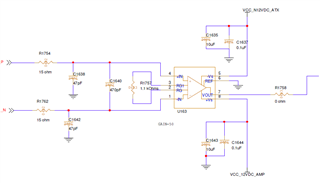
if so need support in reference design with TI part
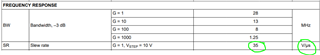
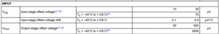
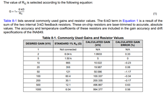
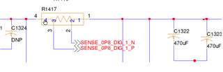
we use high side sensing resistor 0.2mohms. the sense resistor is chosen keeping in mind to measure 1A - 20A static current with 2-3% accuracy at lower end and 1% accuracy at higher end
Hi Muthukumar,
10A/μs across a 200μΩ shunt is equivalent to a voltage slew-rate of 2mV/μs. The slew-rate of INA849 is 35V/μs which is certainly capable of measuring your load transient.
The article you linked seems to be focused on generating high-speed transients rather than measuring high-speed transients.
For your error requirements, you may want to consider increasing the shunt resistance by a factor of 10. The maximum input offset voltage of 35μV on a signal voltage of 200μV produces a significant error.
You mentioned this is a high side current measurement. What is the common-mode voltage at the shunt resistor?
If this is a high voltage measurement, you may want to consider some of our dedicated current-sense amplifiers that are optimized for high-side current measurements.
Regards,
Zach
hi
thanks for quick turn around
there was a correction in my requirements error % in lower side is >30% while high side is <1 %. i.e 1A can be read as 1.3A or so and 20A as 20.5 or less
in that case there wont be need to scale sense resistor right?
Also common mode voltage is very low its around 0.8V.
In the current set up we are facing presence of differential voltage across the sense resistor even though there is no current transients and its siginificantly causing offset in the measurement. how is that possible and how to overcome that?
Hi Muthukumar,
Thanks for the clarification. With these much relaxed error requirements I believe it is not necessary to scale the sense resistor. What is the gain of your INA configuration?
In the current set up we are facing presence of differential voltage across the sense resistor even though there is no current transients and its siginificantly causing offset in the measurement. how is that possible and how to overcome that?
What is the differential voltage that is measured?
What is the expected DC current of the load?
Can you provide a schematic of your circuit?
Thanks,
Zach
hi zach
in our earlier design we used competitor part which i am planning now to replace with TI one but this issue looks independent of part
What is the differential voltage that is measured?
6mv
What is the expected DC current of the load?
NIL or no load
Can you provide a schematic of your circuit?
we have current sense amplifier with high CMRR. G= 100
transient current is sensed using 4 terminal metal resistor.
what i am seeing is ripple from buck output which is in the order of 6mV is getting coupled into this amp as differential signal and hence amplified into 600mV.
if i decouple the sense resistor output to this amp then output is nil and if i give same input to both in amp input then output is nil => CMRR is good. now how can i avoid the ripple getting coupled to this amp without degrading rise time of current
the filters at input of amp is probably have cut off freq in the range of 3-8 MHz.I fi reduce that cut off frequency then transient current rise time will degrade. i need to measure atleast 250ns rise time
Hi Muthukumar,
The CMRR of the INA849 should reject the ripple voltage from the supply and only amplify the differential across the shunt resistor. How are you connecting the shunt resistor to the rest of the circuit during the no load condition?
Can you use an oscilloscope to probe the voltage at each side of the shunt resistor and the INA output?
Also, I notice your schematic is not shown in a gain of 100 V/V. The standard value Rg resistor is 60.4Ω to provide gain of 100 V/V.
Regards,
Zach
yes the gain value is as per calculation the schematic is bit not updated
Can you use an oscilloscope to probe the voltage at each side of the shunt resistor and the INA output
we are seeing 6mV difference before and after the shunt resistor and INA output shows corresponding 6mV * 100 = 600mV output
sense N and sense P goes to the INA input while 4 is to VRM output and 1 is to load our IC
we also use kelvin connection in layout from resistor to INA
Hi Muthukumar,
Please provide the scope captures for my reference at your earliest convenience.
It sounds like you have a 6mV differential voltage across your shunt resistor. The CMRR of the INA849 will not reject differential voltage, only common-mode voltage.
Please use oscilloscope with at least 3 channels to measure the following points in one window.
1.) Sense P (referenced to ground)
2.) Sense N (referenced to ground)
3.) INA OUT pin 7 (referenced to ground)
Thanks,
Zach
hi zach
i will get back with them once i get the setup as they are all occupied and in use i will not be able to measure them.
not sure of immediate days and apologies for that.
Hi Muthukumar,
No problem, I will wait for the scope captures.
Regards,
Zach