This thread has been locked.

If you have a related question, please click the "Ask a related question" button in the top right corner. The newly created question will be automatically linked to this question.

BQ27520-G4: The SOC and RemCap not accurate after learning cycle

Part Number: BQ27520-G4
Other Parts Discussed in Thread: GPCCHEM

Hello,

We had completed the learning cycle using bq27520g4 and a 6000 mAh lithium polymer battery.
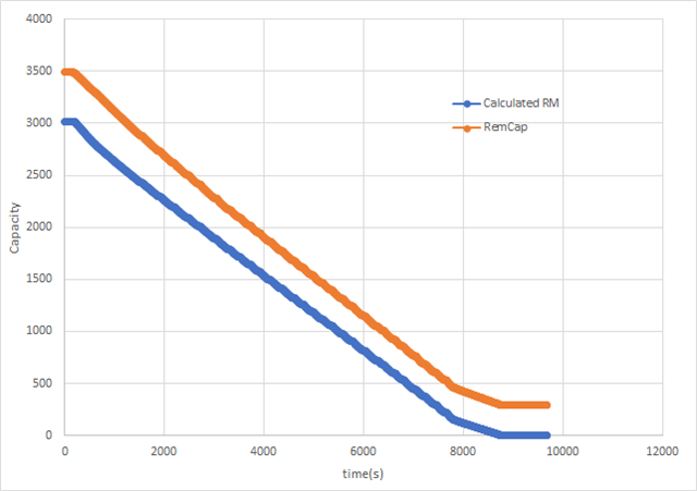
Now we want to estimate the accuracy of the guage. According to the method in this artical, we discharge the battery (the same one used in learning cycle) and record the log.
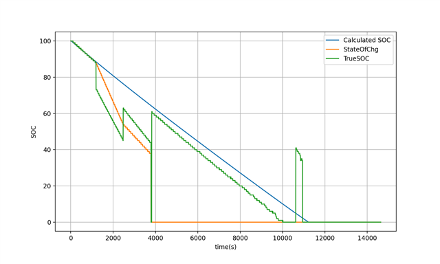
We had do the process twice, but the SOC curves were not correct.
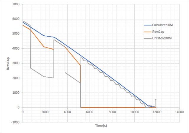
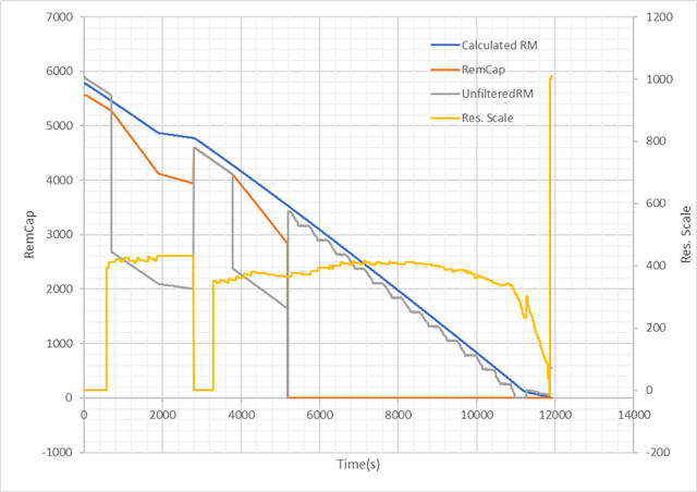
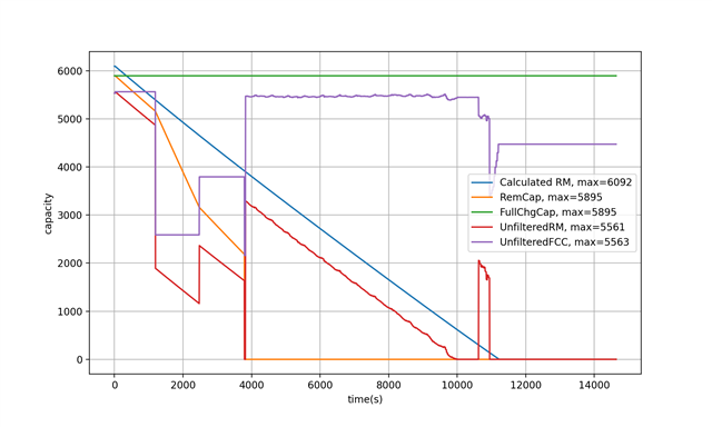
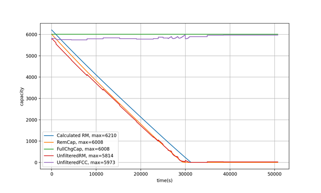
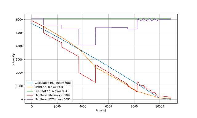
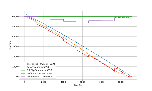
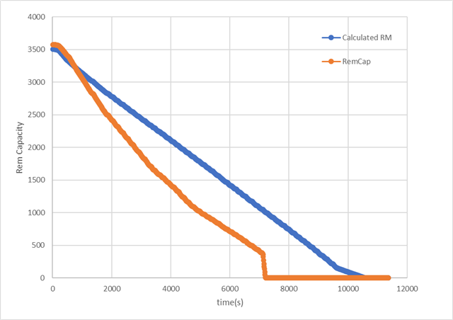
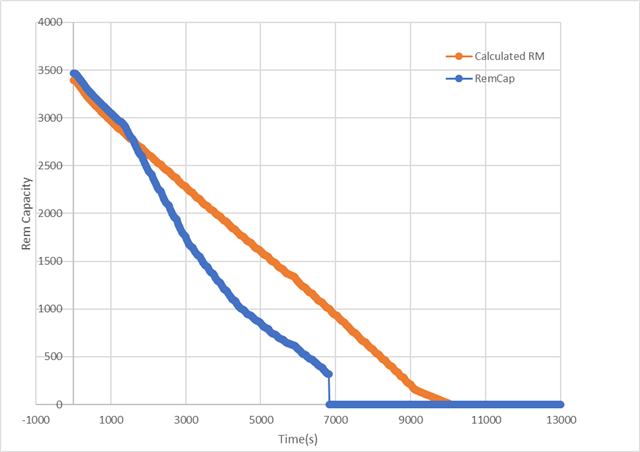
As shown in the record, the RemCap reported by gauge is not match with the Calculated RM.
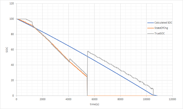
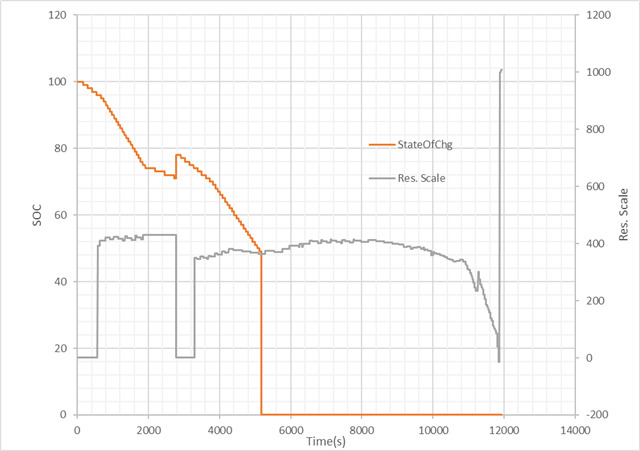
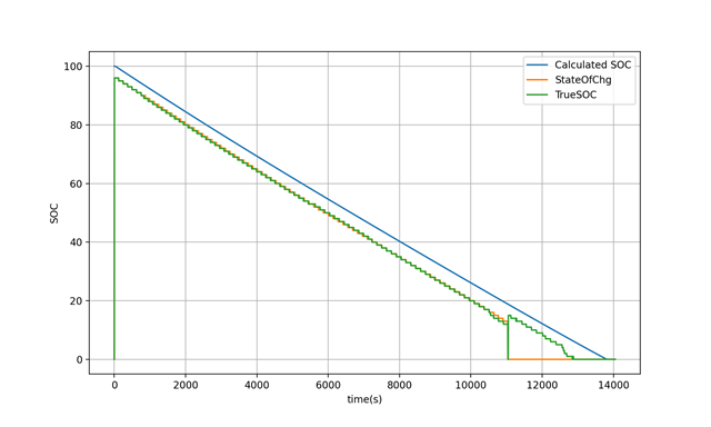
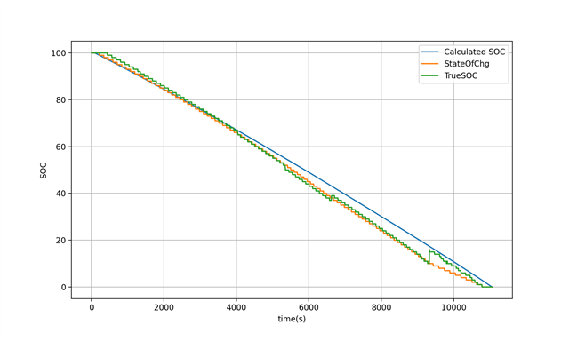
In discharge_log_1, the True_SOC jump from 85% to 75%.
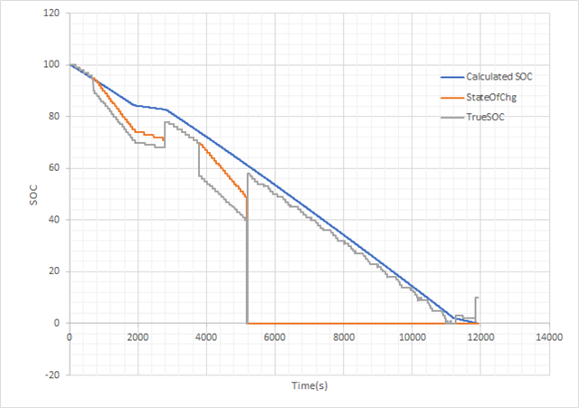
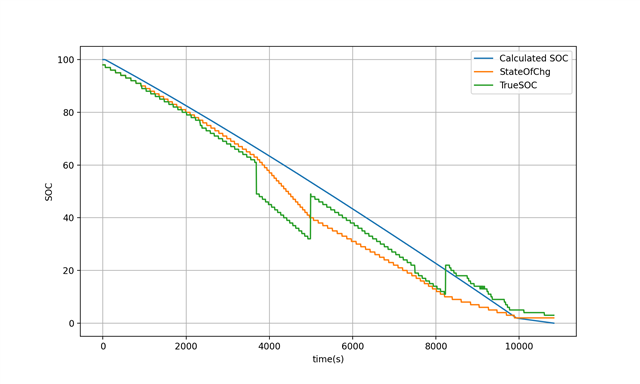
In discharge_log_2, the True_SOC jump from 78% to 63%.
In both log, the SOC jump from 10% to 0%.

The logs are attached.

discharge_log_1.xlsx

discharge_log_2.xlsx

Also, the data memory of our gauge is attached below.

2287.data_memory.gg.csv

Q1. What may cause the mismatch between RemCap and Calculated RM?

Q2. How to avoid the SOC jump from 10% to 0%? Is this related to Fast Resistance Scaling (our Fast Scale Start SOC is set to 10%)? What does Fast Resistance Scaling do?

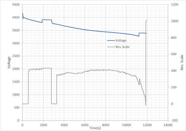
Q3. According to the reference manual, when the voltage reaching the final voltage, the SOC will be force to 0%. Then what's the difference between final voltage and terminate voltage?

Q4. If the power consumption of our system is not constant (as shown in the data log), which leadings to the noise of the voltage, how should we set the final voltage or terminate voltage to make 0% SOC at proper point?

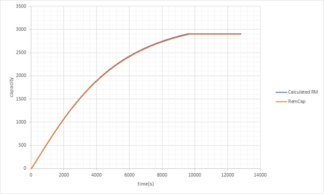
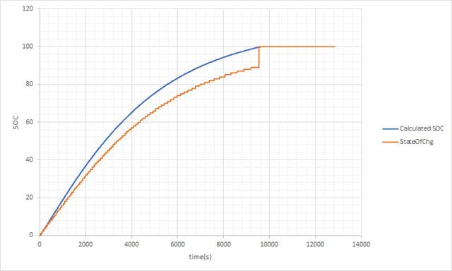
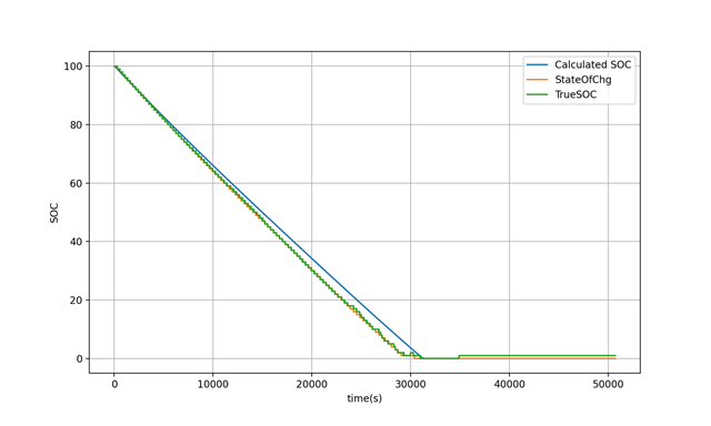
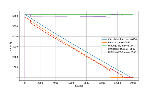
Also, we had also record the log of charging. The RemCap is perfectly accurate, but the SOC curve will jump from 92% to 100%.
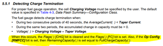
Our system has another protect IC to stop charging while current is lower than 300 mA, so the battery is not actually fully charged. We set the taper current to 310 mA. The jump of SOC from 92% to 100% as the current is lower than taper current, and FC bit is set.

Q5. We wonder if there is some setting to make the SOC curve more smooth and ending at 100% SOC without a jump.

The charge record is attached below.

0005.charge_log.xlsx

Thanks for helping.

Sincerely,
Benjamin Kao

  • Hello Benjamin,

    Was the correct chemistry programmed before running the learning cycle?

  • Hello Shirish,

    The Chem ID we choosed using GPCCHEM is 2375, which is also a 4.2V li polymer battery (but 1800 mAh rather than 6000 mAh of our battery).

    And yes we programmed this Chem ID to the gauge before running the learning cycle.

    Thanks.

  • Hello Benjamin,

    The graph shows RemCap at approx 3500 max. Please check if design capacity is set correctly and Qmax Cell0/1 matches.

  • Hello Shirish,

    Sorry for the late reply.

    The design capacity is set to 6000 mAh, and the Qmax for both cell is 5357 mAh (which is given by the learning cycle).

    I have no idea why the Rem capacity starts from around 3500 mAh during the discharge, but this value is somehow consistent with the calculated RM.

    Thanks.

  • Hello Benjamin,

    A few observations

    Terminate voltage is set at 3400mV and when the gauge jumps to 0%, the log shows that the voltage has fallen below 3400mV at least once.

    Fast scaling is enabled at 10% SOC, therefore the fast scaling triggers at that point. The calculated RM needs to account for voltage dropping below Terminate voltage when current draw is high.

    If you do not want jumps, then I recommend that you set Load mode and Load Select to custom values that match the peak current/power draw of the system. If the system current draw is not predictable, then setting load mode to 2 may help distribute the sudden jump.

  • Hello Shirish,

    Thanks for your advice. After adjusting the terminate voltage to 3200 mV, we can get a RemCap curve parallel to the calculated RM during discharge as in the figure. Now I think we need to adjust the reserved cap to let the two curve match.

    Another question about charging. There is a protect IC in out system, and it will stop charging when the current is below 300 mA. So I set the taper current to 310 mA. The record shows the RemCap is the same as calculated RM, but the gauge reported SOC will jump from 90% to 100% when the current is lower than the taper current.
    Is there some parameters I can adjust to let the SOC curve smoother?


    The charging record is attached below.
    charge_log_5.xlsx

    Sincerely,
    Benjamin Kao

  • Hello Benjamin,

    This looks like it occurs when the the charge termination happens, you can see the FC flag is set and SOC jumps because the RMFCC configuration bit is set in Op Config.

    The gauge needs to learn the capacity at full charge, so on the next cycle it should be resolved. If you changed the Reserve Capacity without cycling the battery or performing a relaxation with DOD reading this may be what occurred.

    Sincerely,

    Wyatt Keller

  • Hello Wyatt,

    Thanks for your explanation. I was testing different guage parameters at that time, and I will try to use the same parameters for multiple cycle to see if this problem still happen.

    Another question, I use a new battery to do the learning cycle, then I do the discharge to test the accuracy of the gauge. This time, I set the terminate voltage = 3100 mV, which never reached during the process of discharge. But the SOC reported by gauge drop to 0 at half of the discharge.

    I also found the TrueSOC drop to 0 at that point, but recover to 58% after that drop. Also the UnfilteredFCC changed wierd during thar peroid. But the discharge conditions (current, voltage, temperature) didn't change during that peroid. Thus I can't fond the reason for this to happen.

    The discharge log and the data memory setting is attached below. Could you give me some hint on what's happening?

    5008.discharge_log_1.xlsxdata_memory_discharge_1.gg.csv

    Thanks.

    Sincerely,

    Benjamin Kao

  • Hello Benjamin,

    Did you take a golden image after learning with the first battery and use that? Otherwise you will get random results.

    Make sure that the new batteries are of the same chemistry.

  • Hello Shirish,

    Yes, I did take a golden image on the PCB that used to run the learning cycle, then install the golden image to the second PCB that I used to run the accuracy test.

    And the exactly same battery is used in the learning cycle and the accuracy test.

    The following is another accuracy test I did. The UnfilteredRM and the TrueSOC is actually close to the calculated value if no wierd things happen.

    Have you encounter this problem before?

    1200.discharge_log_2.xlsx

    Thanks.

    Benjamin Kao

  • Hello Benjamin,

    You may want to look at the smoothing settings 5.1.16 SOC Smoothing

    and 5.1.14 Fast Resistance Scaling

  • Hello Shirish,

    I had enable the SOC Smoothing, but since the UnfilteredRM jumps a lot, so I think my problem is not related to the SOC Smoothing.

    The Fast Resistance Scaling is enable, and my Terminate Voltage=3100 mV, and Term V Delta=200 mV, Fast Scale Start SOC=10 %, which is the default value.

    I found that the Res. Scale rise up almost at the same time as the UnfilteredRM drops a lot. Does this means my problem is caused by the Fast Resistance Scaling?

    But the voltage not drop below 3300 mV (Terminate Voltage + Term V Delta) when the Res.Scale becomes non zero at about 600 seconds. Also The StateOfChg not fall below 10%. Does this mean that the Fast Resistance Scaling is enable incorrectly? Should I disable it?

    Thanks.

    Benjamin Kao

  • Hello Benjamin,

    I do not think Fast resistance scaling is active in this case. I would suggest that you program the golden image again and check with the original cell. If that gives good results then the new cell is different.

  • Hello Shirish,

    You are right, turn off resistance scaling did not solve my problem, and the unfilteredRM still jumps a lot.

    I did some more experiment using the original board and the original battery which I performed the learning cycle on.

    In the first experiment, I useed 1.66 ohms resistor to discharge the battery, and I encountered the same problem as I used our system to discharge the battery.

    The 1.66 ohms resistor can get around 2000 mA of current, which is on the same level as our system's true load.

    The unfilteredRM and unfilteredFCC just jump all around, and make the filtered RemCap and SOC become 0 around 4000 secs.

      discharge_log_8.csv

    In the second experiment, I use 5 ohms resistor to discharge the battery.

    The 5 ohms resistor is which I used to perform the learning cycle, which can get around 700 mA of current.

    Althouth there are still some jitter on the unfilteredRM and unfilteredFCC, but the result is good enough compare to the first experiment.

      discharge_log_9.csv

    Does this result means I should use a smaller resistor to perform the learning cycle? The start guide SLUA902 says the discharge current should be between C/5 and C/10, so I use the 5 ohms resistor to discharge. But the typical load of our system is more like a C/3.

    Do you have any advice on how to deal with this inconsistent accuracy between using different discharge current?

    Thanks.

    Benjamin Kao

  • Hello Benjamin,

    Yes, the learning cycle load should be between c/5 and C/10. You take the golden image after a successful learning cycle.

    Then you can use the system load for checking accuracy.

  • Hello Shirish,

    I had done another learning cycle with a 3.33 ohms resistor, and the learning cycle is done with the update status = 02. I created a golden image then programed it back to the system.

    Then I use a 2 ohms resistor to discharge the battery and test the accuracy, The system and the battery are the exactly same, the original one which I performed the learning cycle on.

    But I still gets a FCC jump near the end of the discharge.

    I had attached the log and the .gg.csv file for the golden image I generated.

    discharge_log_10.xlsx

    data_memory_after_learn_cpoied_status.gg.csv

    ========================

    I wonder if the not so perfect Chem ID will leads to this problem.

    In the begining, I used GPCCHEM to find the Chem ID with a used battery, the report is attached below, and it said:

    `Best chemical ID : 2375 Best chemical ID max. deviation, % : 5.39`

    Although it had a max deviation larger than 3%, the founded battery is a 4.2V Li-poly battery. My battery is also a Li-poly battery.

    8666.GPC_report.txt
    Chemistry ID selection tool, rev=2.52		
    		
    Configuration used in present fit:		
    ProcessingType = 2		
    NumCellSeries = 1		
    ElapsedTimeColumn=0		
    VoltageColumn = 1		
    CurrentColumn = 2		
    TemperatureColumn = 3		
    		
    Best chemical ID : 2375	Best chemical ID max. deviation, % : 5.39	


    Summary of all IDs with max. DOD deviation below 3%		
    		
    Chem ID	max DOD error, %	Max R deviation, ratio
    0	0	0
    		
    Warning: Deviation is above recommended level. New chem ID needs to be released for this cell. Please contact your TI representative to send the cell to Dallas for characterization		
    		
    		
    Selection of best generic ID for ROM based devices like bq274xx		
    		
    		
    Device / Family #1		
    Generic Chem ID	Device/ Voltage/ Chemistry	max DOD error, %
    3142	bq27421-G1D: 4.4V LiCoO2	12.31
    354	bq27411-G1C: 4.35V LiCoO2	15.56
    128	bq27421-G1A: 4.2V LiCoO2	18.35
    312	bq27421-G1B: 4.3V LiCoO2	30.19
    Best generic ID 3142		
    Warning: Deviation for best generic ID is above recommended level for this device / family. Consider using another device, flash based gauge or RAM programming of custom ID.		
    		
    		
    Device / Family #2		
    Generic Chem ID	Device/ Voltage/ Chemistry	max DOD error, %
    1210	bq27621:  (ALT_CHEM1) 4.3V LiCoO2	14.85
    354	bq27621:  (ALT_CHEM2) 4.35V LiCoO2	15.56
    1202	bq27621: (default) 4.2V LiCoO2	16.29
    Best generic ID 1210		
    Warning: Deviation for best generic ID is above recommended level for this device / family. Consider using another device, flash based gauge or RAM programming of custom ID.		
    		
    		
    Device / Family #3		
    Generic Chem ID	Device/ Voltage/ Chemistry	max DOD error, %
    3142	bq27426: (ALT-CHEM2) 4.4V LiCoO2	12.31
    1202	bq27426: (ALT_CHEM1) 4.2V LiCoO2	16.29
    3230	bq27426: (default) 4.35V LiCoO2	16.81
    Best generic ID 3142		
    Warning: Deviation for best generic ID is above recommended level for this device / family. Consider using another device, flash based gauge or RAM programming of custom ID.		


    After a while, I used the GPCCHEM with a new battery to find the Chem ID, and it said:

    `Best chemical ID : 1280 Best chemical ID max. deviation, % : 3.01`

    But it seems to refer to a Li-ion battery, while mine is a Li-poly battery, so in the end I use 2375 as my Chem ID, and the learning cycle is successful.

    20836.GPC_report.txt
    Chemistry ID selection tool, rev=2.52		
    		
    Configuration used in present fit:		
    ProcessingType = 2		
    NumCellSeries = 1		
    ElapsedTimeColumn=0		
    VoltageColumn = 1		
    CurrentColumn = 2		
    TemperatureColumn = 3		
    		
    Best chemical ID : 1280	Best chemical ID max. deviation, % : 3.01	


    Summary of all IDs with max. DOD deviation below 3%		
    		
    Chem ID	max DOD error, %	Max R deviation, ratio
    0	0	0
    		
    Warning: Deviation is above recommended level. New chem ID needs to be released for this cell. Please contact your TI representative to send the cell to Dallas for characterization		
    		
    		
    Selection of best generic ID for ROM based devices like bq274xx		
    		
    		
    Device / Family #1		
    Generic Chem ID	Device/ Voltage/ Chemistry	max DOD error, %
    354	bq27411-G1C: 4.35V LiCoO2	16.73
    3142	bq27421-G1D: 4.4V LiCoO2	23.61
    128	bq27421-G1A: 4.2V LiCoO2	41.54
    312	bq27421-G1B: 4.3V LiCoO2	48.97
    Best generic ID 354		
    Warning: Generic ID Deviation is so high that it is most likely due to anomaly in the data. Please check that data files have recomended format, units and test schedule		
    		
    		
    Device / Family #2		
    Generic Chem ID	Device/ Voltage/ Chemistry	max DOD error, %
    1210	bq27621:  (ALT_CHEM1) 4.3V LiCoO2	15.24
    354	bq27621:  (ALT_CHEM2) 4.35V LiCoO2	16.73
    1202	bq27621: (default) 4.2V LiCoO2	28.12
    Best generic ID 1210		
    Warning: Generic ID Deviation is so high that it is most likely due to anomaly in the data. Please check that data files have recomended format, units and test schedule		
    		
    		
    Device / Family #3		
    Generic Chem ID	Device/ Voltage/ Chemistry	max DOD error, %
    3230	bq27426: (default) 4.35V LiCoO2	13.94
    3142	bq27426: (ALT-CHEM2) 4.4V LiCoO2	23.61
    1202	bq27426: (ALT_CHEM1) 4.2V LiCoO2	28.12
    Best generic ID 3230		
    Warning: Deviation for best generic ID is above recommended level for this device / family. Consider using another device, flash based gauge or RAM programming of custom ID.		


    If the learning cycle is successful, does the deviation of the Chem ID still matter?

    Should I send my battery to TI for a new Chem ID? How long will it take to make a new Chem ID for it?

    Thanks.

    Benjamin Kao

  • Hello Benjamin,

    ChemID logs for matching with GPCCHEM tool must be taken with new cells. The cells must not have any protectors or other circuitry connected to it. You would choose the best chemID that is in the report. Assuming that the second cycle is run with bare cells you should use 1280. However we want the deviation to be less than 3%, so if you cannot find a match within 3%, then it may be a new ChemID that needs characterization.

    Let me know what you find when you cycle a brand new cell with nothing else connected to it.

  • Hello Shirish,

    The battery cell we used has a protect (from over charge, over discharge and short) curcuit built in, and we cannot remove it.

    We had use Chem ID 1280, and a 3.33 ohms resistor to discharge during the lerning cycle.

    We use a new cell to do the learning-cycle, let me call it golden_image_1, but the result is still not perfect.

    The discharge record below was perfromed with golden_image_1 and the new battery cell. It shows a drop in TrueSOC, unfilteredRM and unfilteredFCC at about 60%~50% SOC.

    We also use the same setting, but with a used battery cell, to run the learning cycle, which is golden_image_2.

    The discharge record below was performed with golden_image_2 and new battery cell.

    The result seems better than the result with golden_image_1.

    We also wonder if this result is normal for the gauge, or the result should be more smooth?

    The record during two learning cycle are attached below, we think they are very similar, so we don’t know what makes golden_image_1 worse.

    learning_record_1.xlsxlearning_record_2.xlsx

    We also wonder if we can edit the Ra table directly to smooth the drop? Does the FCC and RM drop caused by overestimated resistance of the battery? If we lower the Ra value, would the result be better?

    Thanks for your help.

    Benjamin Kao

  • Hello Benjamin,

    For chemistry matching, you will need to remove the protector. The results are off because the protector is not characterized and it has different loading at different points in the battery curve.

  • Hello Shirish,

    If we can remove the protector to find the matching Chem ID, should the protector be removed during learning cycle?

    Thanks.

    Benjamin Kao

  • Hello Benjamin,

    The protector should be removed only for chemiID matching. Protector should be connected back for learning cycle.