[FAQ] AM625 / AM623 / AM625SIP / AM625-Q1 / AM620-Q1 Custom board hardware design – Queries regarding VPP eFuse programming power supply selection and application

Other Parts Discussed in Thread: AM62P, AM62A3, AM62A7

Hi TI Experts,

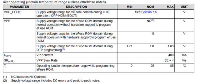
I have the below queries regarding the VPP supply selection, configuration and application connected to the VPP pin of the SoC.

  1. When is VPP required
  2. Difference between GP and HS-FS hardware boards
  3. What are the VPP voltage and current specs?
  4. What is the recommended VPP supply solution?
  5. Can I use a load switch or FET to switch the supply?
  6. LDO specs to consider.
  7. Should i use a dedicated supply?
  8. Steps for eFuse programming
  9. How should I terminate the VPP supply pin for GP devices with no HS-FS provision?
  10. How should I terminate the VPP supply pin for HS-FS device used as a GP device?
  11. How should I terminate the VPP supply for HS-FS devices when not programming the eFuse
  12. Any suggestion for reducing OTP write failure.
  13. Do you have any additional recommendations?
  14. Does the above guidelines apply for AM64x, AM62A7, AM62A3, AM62P and AM62Px devices?
  15. On the SK TLV75518PDQNR is used. Is there an LDO recommendation for automotive applications?

Let me know your thoughts.

  • Hi Board designers, 

    Refer below inputs for the VPP supply related queries.

    1. When is VPP required

    The VPP is used to program the eFuse when HS-FS devices are used.

    SoC devices come in two types: General Purpose (GP) & High Security (HS). All GP devices can leave the VPP domains unconnected per DM. Pre-programmed HS devices can also leave VPP supply unconnected if no additional eFuse programming is needed. If it is required to do on-board eFuse programming, VPP supply is required.

    1. Difference between GP and HS-FS hardware design

    The key difference is the SOC and the VPP configuration. You need to supply the VPP supply rail during the time that eFuses are programmed,


    1. What are the VPP voltage and current specs?

    Refer section in the datasheet: 7.9.1 Recommended Operating Conditions for OTP eFuse Programming. 

    1. What is the recommended VPP supply solution?

    An LDO low-dropout with fast transient response, quick output discharge and capability to enable to output is recommended.  PMIC with LDO output meeting the datasheet ROC (Recommended operating conditions) can be used.

    A fixed LDO is recommended. When an adjustable LDO is used, consider adding a protection diode at the output and provide a provision to isolate the LDO output connected to the processor VPP supply pin. Test the LDO output performance before connecting the LDO output to the VPP supply pin.  

    1. Can I use a load switch or FET to switch the supply?

    Given the transient current requirement during eFuse programming, load switch or FET switch may not be a recommended approach, It is recommend using a 400mA LDO.  A load switch is likely to have too much voltage drop that can't be compensated like when using an LDO.

    1. LDO specs to consider?

    The 1.8V source for VPP should have an internal active discharge function that gets turned on when the source is disabled to ensure VPP is held to 0V during normal operation.

    1. Should i use a dedicated supply?

    The VPP voltage is not recommended to be supplied when the eFuse write is not being done.

    VPP should only be powered while security key programming is done.  It should be powered off during all other times, including normal active use of the SoC.  This is the reason for VPP supply not being shared with other peripherals, which are required to be powered at all times.

    1. eFuse programming steps

    An OTP (One Time Programmable) Keywriter (software tool) is used to program the eFuse. The keywriter  controls the On-Board LDO that is used to generate the VPP supply voltage via a GPIO output.

    An alternative way to source the VPP is to use an external supply. The required caps and termination/Discharge resistor are recommended to be placed near to the SoC VPP pin. 

    A custom VPP Programming board using an LDO similar to the On-Board LDO used in the EVM can be designed and the LDO can be enabled via the GPIO output. 

    https://www.ti.com/lit/zip/sprr275 

    (refer to file VPPPROGRAMMINGBOARD_3J0002_REV1_0A.PDF).  

    Recommended LDO

    https://www.ti.com/product/TLV755P/part-details/TLV75518PDQNR

    In case an external power supply is used, The GPIO output can be used to control or time the external power supply output.

     Programming sequence for OTP eFuses:
    • Power on the board per the power-up sequencing. No voltage should be applied on the VPP terminal during power up and normal operation.
    • Load the OTP write software required to program the eFuse (contact your local TI representative for the OTP software package).
    • Apply the voltage on the VPP terminal (according to the specification in Section 7.9.1 of the datasheet).
    • Run the software that programs the OTP registers.
    • After validating the content of the OTP registers, remove the voltage from the VPP terminal.

    Reference: Section 7.9.3 Programming Sequence of datasheet

    1. How should I terminate the VPP supply pin for GP devices?

    Do not connect the SOC VPP pin. Leave it open. Alternatively, you could terminate to ground externally.

    1. How should I terminate the VPP supply pin for HS-FS device used as a GP device?

    Used as GP device and could be used as HS-FS device in the future

    Provide a provision to add a discharge resistor 1K.  The pull-down value needs to be to select such that it doesn't allow any leakage path through the LDO to source a potential greater than 0V when disabled.

    Provide provision for low loop inductance bulk (2.2 uF) + decoupling (0.1 uF) capacitor(s) located near the VPP pin.

    Populate the discharge resistor and DNI the capacitors.

    Used as only GP device (no HS-FS)

    The VPP pin can be left open or a 1K resistor can be added with a TP for Just in case usage.

    1. How should I terminate the supply for HS-FS devices when not programming the eFuse

    The VPP power rail is required to be powered during the programming of the eFuse array.  It should not be powered during normal operation. An always VPP supply is not allowed or recommended. 

    Device reliability was never evaluated for an operating condition where the VPP power rail was connected to an always on power source.  Take care to connect the LDO to a GPIO such that it defaults to the off state and the TI keywriter software will apply power to VPP when appropriate.


    1. Any suggestions for Reducing OTP write failures.

    The VPP power rail requires a high transient current to blow the metal fuses in the eFuse array, so it would be almost impossible to maintain the ROC voltage range on the VPP pin without providing a very low loop inductance bulk decoupling capacitor(s) located near the VPP pin.  It is important the customer validate VPP never drops below the min ROC value during programming to ensure the fuses are burned properly. The fuses may appear to be blown but could be marginal if the VPP is allowed to drop below the min ROC value even for the shortest period of time during programming. VPP supply has to be characterized to ensure they are within the ROC during programming.


    1. Do you have Any additional recommendations?

    Refer the below section of the device specific datasheet.

    7.9 VPP Specifications for One-Time Programmable (OTP) eFuses

          14. Does the above guidelines apply for AM64x, AM62A7, AM62A3, AM62P and AM62Px devices?

    It is Ok to follow the described guidelines/recommendations for the above-mentioned devices

         15. On the SK TLV75518PDQNR is used. Is there an LDO recommendation for automotive applications?

    Load Transient characteristics is required to be comparable to the power supply used in the SK (TLV75518PDQNR).

    or other automotive LDOs another recommendation would be TPS7A21-Q1 which showcases good transient response.

    Currently, we are sampling the 1.8V output option of this LDO, P7A2118PQWDRBRQ1. The full release MPN of this LDO will be TPS7A2118PQWDRBRQ1.

    Note on LDO selection 

    TLV75518PDQNR is  device in DQN Package, 4-Pin X2SON

    Refer below device outline 

    There is a likely chance of assembly error due to the LOD outline, pins orientation 

    and the land pattern (pads and pitch)

    Note: An alternate package could be selected based on the space availability can be chosen. Alternative be sure to include the LDO assembly caution note during board assembly. 

    eFuse programming supply use case summary 

    The VPP pin is only allowed to be powered during programming.  So the system design must provide a way for software to only apply power during programming of the eFuse array. We do not recommend a load switch or a DC/DC source due to the high transient currents required to blow the fuses. We recommend the VPP pin be sourced directly from a dedicated LDO that has good transient response.  Even then the system designer needs to validate their specific solution doesn’t allow the VPP pin on the processor to ever drop (not even for a very short period of time) below the minimum ROC voltage while programming the eFuse array. They may need to minimize trace inductance and/or increase decoupling capacitors as necessary to ensure this operating condition.  This is the reason it is not possible to power VPP from a shared power source.

    Additional References 

    https://e2e.ti.com/support/processors-group/processors/f/processors-forum/1352842/am625-am625-am623---vpp-usecase

    Regards,

    Sreenivasa

  • Hi Board designers, 

    Refer below additional inputs for the VPP supply related queries.

    16. We need to supply all the power of SOC while we're writing, right? Or should we just supply VPP power?

  • HI Board designers,

    Refer below additional queries answered

    1. The VPP is supplied during factory process, can this cause any OTP writing failure?

    Using external supply should not be a concern. it is important to follow the power sequencing requirements. The SOC supplies should have ramped up and be stable before applying the VPP. It is recommended to switch off the VPP before switching off the SOC supply. Since an external voltage source is used, a 2.2 uF + 0.1 uF cap is recommended near to the SOC VPP pin due to the load current transient requirements.

    Also note the below inputs i received from the device expert:

    All customers must validate their VPP source impedance and confirm it never allows the AM62x VPP pin to drop below the min value defined in the ROC table for any period of time during eFuse programming.  The VPP transient current is very high short duration pulses so this validation is very important to ensure the fuses in the eFuse array are properly burned.

    1. How close in time should the VPP supplied before the OTP writing starts? The idea here is to drive the VPP by a external source before we download the keywriter routine then remove the supply after the keywriting is complete. We would not be using any internal trigger signal from the soc.

    The recommendation is to use an SOC IO to time since this ensure the power sequence in additional to the ON time. It should be OK to have the VPP supply ON for few seconds before the key writer routine is executed and switch off a few seconds after the key writing routine is executed. The key is the VPP supply should be within the ROC all the time and also the supply sequencing is followed.

    Note on Keeping VPP on for longer than required time:

    The biggest concern with apply a potential to VPP when not programming the eFuse array is an increased probability that the eFuse array could accidently be programmed if something unexpected happens and rouge code writes to the eFuse array.  There should not be any problem if they ensure this never happens.

    AM62A3-Q1: VPP while writing

    ①If we interrupt writing in the middle, is it possible to start writing again from the beginning?

    →No. It is impossible.

    →In case of power failure of VPP/SoC during the function Sciclient_service() execution, the consequence is unexpected, and most likely, it is impossible to re-run key programming again.

    ②What kind of problems can be expected if there is a power loss in the middle of writing?

    → In case of power failure of VPP/SoC during the function Sciclient_service() execution, the consequence is unexpected

    ③How can we check if the writing was successful? Is there a register to store the write results?

    →***I should ask another thread.***

    ④We need to supply all the power of SOC while we're writing, right? Or should we just supply VPP power?

    →SOC is expected to be supplied with all supplies. the supplies are expected to be ramped and stable.

    ⑤Is it possible to control the GPIO of the AM62A while writing?

    →Yes. the LDO EN is controlled by the GPIO.

    Yes. R5 SRC code is owned and re-buildable by user, and it is possible to configure peripheral, i.e. GPIO in R5 code.


    Regards,

    Sreenivasa