Part Number: AWR1642BOOST-ODS
I would like to try the obstacle detection demo from the mmWave sensor automotive toolbox, but I want to make absolutely sure I will be able to revert firmware back to the out-of-box demo that comes pre-installed on the AWR1642BOOST ODS evaluation board, as it currently works with the online mmWave demo visualizer.
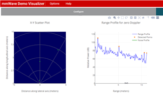
I am already able to build both the obstacle detection demo DSS and MSS projects from the Automotive Toolbox (3.6.0), which has its own standalone visualizer application. This tells me my environment is set up correctly, at least for the obstacle detection demo.
I can build the Out Of Box 16xx MSS project from the Industrial Toolbox (4.10.1), but get the following message at the end of the build during the link process for the Out of Box 16xx DSS project - note that everything compiles just fine up to this point:
<Linking>
warning #10247-D: creating output section ".l3data" without a SECTIONS specification
warning #10247-D: creating output section ".l2data" without a SECTIONS specification
warning #10247-D: creating output section ".l1data" without a SECTIONS specification
warning #10247-D: creating output section ".demoSharedMem" without a SECTIONS specification
warning #10247-D: creating output section "systemHeap" without a SECTIONS specification
error #10099-D: program will not fit into available memory. run placement with alignment fails for section "systemHeap" size 0x5000 . Available memory ranges:
L2SRAM_UMAP1 size: 0x20000 unused: 0x0 max hole: 0x0
L2SRAM_UMAP0 size: 0x20000 unused: 0x438d max hole: 0x4360
L1PSRAM size: 0x4000 unused: 0x4000 max hole: 0x4000
L1DSRAM size: 0x4000 unused: 0x4000 max hole: 0x4000
L3SRAM size: 0xc0000 unused: 0x0 max hole: 0x0
HSRAM size: 0x8000 unused: 0x0 max hole: 0x0
undefined first referenced
symbol in file
--------- ----------------
_MmwDemo_fastCode_L1PSRAM_copy_table ./dss_main.oe674
>> Compilation failure
makefile:168: recipe for target 'xwr16xx_mmw_dss.xe674' failed
error #10234-D: unresolved symbols remain
error #10010: errors encountered during linking; "xwr16xx_mmw_dss.xe674" not built
gmake[2]: *** [xwr16xx_mmw_dss.xe674] Error 1
makefile:164: recipe for target 'main-build' failed
gmake[1]: *** [main-build] Error 2
makefile:159: recipe for target 'all' failed
gmake: *** [all] Error 2
**** Build Finished ****
These are the versions of build tools I have installed:

I am using Code Composer Studio Version: 11.1.0.00011.
I changed heapMemParams.size in dss_mmw.cfg from 0x5000 to 0x4000 (based on the dynamic memory hole sizes given by the linker output), and removed the "extern" from the declaration of _MmwDemo_fastCode_L1PSRAM_copy_table in dss_main.c, and now the project builds successfully, and I get xwr16xx_mww_dss.bin.
Is this the correct out of box binary for the AWR1642BOOST ODS board, and why does it not build correctly without these two edits?
Part Number: TMAG5231
For this example, we will emulate a mechanical hinge movement similar to what is used in consumer laptops for lid position sensing. Advantages of this implementation include small form factor design, and ease of assembly/implementation. The use of the omnipolar switch enables the same output at BOP and BRP regardless of the magnet being north or south oriented. The omnipolar switch selection makes assembly of mechanical systems easier as the magnets do not need to be oriented one specific way for the device to function properly; nor does the sensor have to be adjusted or programmed to be used with the specific magnet north/south pole orientation.
In the tool, we will implement a north or south facing block magnet moving on a 200mm arc radius hinge near an omnipolar switch. The magnet is a N35 block with 2.5 mm length and 5mm dimensions for width, and thickness. The displacement dimensions range from 20 degrees (d1) to 0 degrees(d2) with a -8mm sensor Z-offset. The TMAG5231B1 omnipolar switch in SOT-23 package will be used for the simulations. To prove operational characteristics of the omnipolar switch, results will be created for both a north and south oriented magnet. Figure 1 represents configuration settings for a south facing magnet, and Figure 2 represents north facing. Enter desired configuration settings into the tool, and generate results for the simulation by selecting “Calculate B-Field & Vout”.
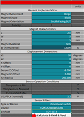
Figure 1: South Facing Magnet Implementation
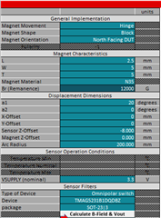
Figure 2: North Facing Magnet Implementation
Figure 3 demonstrates the physical movement for the hinge simulation.
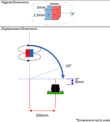
Figure 3: Simulation Movement Representation
The below waveforms represent the sensor output and B-Field plotted with respect to hinge angle.
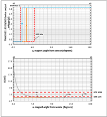
Figure 4: South Facing Magnet Output Results
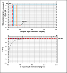
Figure 5: North Facing Magnet Output Results
As displayed in Figure 4 and Figure 5, the output results are identical for the omnipolar device regardless of magnet N/S orientation.
For additional information on hinge transition detection, see this application brief on the topic: Transition Detection Using Hall-Effect Sensors
Previous FAQ, Part Two: Simulating Slide-By movement with a ratiometric PWM sensor
Part Number: DRV5057
For the second example, we will emulate a mechanical slide by movement similar to what can be found in analog dimming switches. Advantages of this implementation include a PWM output signal, and no mechanically wearing items. The use of this hall sensor enables the PWM output to be fed into a microcontroller without requiring an ADC or external signal chain components.
For the simulation, we will implement a NS facing cylinder magnet moving slide-by near a linear PWM ratiometric hall sensor. The magnet is a N42 cylinder with a 5mm radius and 5mm thickness. The displacement dimensions range from -10mm(d1) to 10mm(d2) with no X or Y offset from the center of the package. The DRV5057A ratiometric PWM output hall sensor will be used for the simulations. Alternatively, the DRV5055A can be used if analog output is required. Figure 1 displays the input configuration for the simulation. Enter desired configuration settings into the tool, and generate results for the simulation by selecting “Calculate B-Field & Vout”.
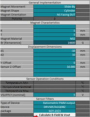
Figure 1: Slide-By Magnet Implementation
Figure 2 demonstrates the physical movement for the slide-by simulation.
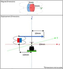
Figure 2: Simulation Movement Representation
For complex magnet shapes such as the cylinder and sphere, FEMM will be used for the magnetic field simulations. Following the selection of “Calculate B-Field & Vout”, a popup will appear requiring naming for the FEMM project and a selection of file location for the results. Populate these fields, and select “Next”.
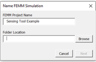
Figure 3: FEMM Simulation Folder Location
Select “Open FEMM” in the popup to start the simulation.
Before the simulation concludes, a popup will appear allowing the user save an image of the flux density plot from the FEMM simulation.
Figure 4: Flux Density Plot Prompt
Select “Close FEMM” to view the results in Excel.
Figure 5: FEMM Close Prompt
The below waveform represents the sensor output in % PWM plotted with respect to horizontal magnet position.
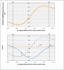
Figure 6: DRV5057 Output Results
As displayed in Figure 6, the PWM duty cycle varies with respect to horizontal magnet position varying from approximately 25% to 75% duty cycle. The analog PWM range can be adjusted via device selection, or by altering the magnetic characteristics of the simulation.
For more information on Slide-By sensing, see this Application Brief on the topic: Tracking Slide-By Displacement with Linear Hall-Effect Sensor
Previous FAQ, Part one: Simulating head-on movement with a unipolar switch.
Next FAQ, Part Three: Simulating hinge movement with an Omnipolar hall-effect switch
Part Number: TMAG5124
Ensure both FEMM and the Magnetic Sensing Proximity Tool are downloaded to conduct magnetic simulations using the tool.
See this E2E FAQ for download of the Magnetic Sensing Proximity Tool: Tool FAQ
FEMM can be downloaded from the link included here: FEMM Download
For the first example, we will emulate a mechanical head-on sensing movement similar to what can be found in magnetic two-state switches. Advantages of this implementation include small size, wide selection of suitable devices, and contactless position sensing. The use of a unipolar switch enables the system to be cost efficient, with the device sensitivity dictating the operating points of the hall switch.
For the test, we will implement a south facing block magnet moving head-on towards a unipolar switch. The magnet is a N35 cube with 5mm dimensions for length, width, and thickness. The displacement dimensions range from 10mm(d1) to 30mm(d2) with no X or Y offset referenced to the center of the package. The TMAG5124A unipolar switch in SOT-23 package will be used for the simulations. Figure 1 displays the input configuration for the simulation. Enter desired configuration settings into the tool, and generate results for the simulation by selecting “Calculate B-Field & Vout”. Note, any simulation involving a block magnet will not utilize FEMM for the B-Field calculation. Therefore, it is possible to conduct this specific test with only the Magnetic Sensing Proximity Tool installed.
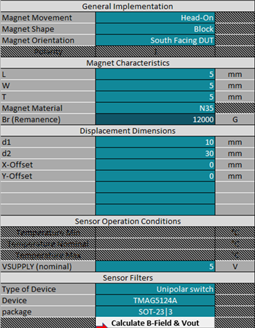
Figure 1: Head-On Magnet Implementation
Figure 2 demonstrates the physical movement used for the head-on simulation
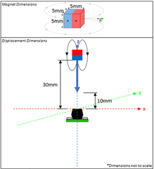
Figure 2: Simulation Movement Representation
Figure 3 represents the sensor output and B-Field(X,Y,Z) plotted with respect to magnet position.
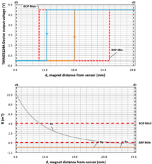
Figure 3: Head-On Output Results
The output waveform demonstrates typical switching behavior at 19.9mm for a low to high transition, and 15.1mm for high to low.
For additional information on developing a two-state switch, see this application brief covering the topic: Two-State Selector Using Hall-Effect Sensors
For additional information on using a head-on sensing movement, see this application brief covering the topic: Head-on Linear Displacement Sensing Using Hall-Effect Sensors
Next FAQ, Part Two: Simulating slide-by movement with a ratiometric PWM Hall-Effect sensor
Hello Everyone
The new mmWave Industrial Toolbox Version 4.10.1 is now live on TIREX. This package includes both new content and updates to existing material. The full release notes can be found below.
Industrial Toolbox 4.10.1
-------------------------------------------------------------------------------------------------------
The following Labs have been updated in this toolbox:
-------------------------------------------------------------------------------------------------------
Industrial Toolbox 4.10.0
-------------------------------------------------------------------------------------------------------
The following Labs have been updated in this toolbox:
People Counting with Vital Signs
Part Number: TMAG5123
Hall-effect switches are simple position sensing solutions, which indicate the presence or absence of a magnet, and can be used in a variety of different applications across the market. You can imagine the endless amount of electromechanical systems these sensors are expected to fit into that alter the device selection criteria, such as magnetic characteristics, power consumption, package type and size. However, one particular feature that isn’t discussed enough is the axis of sensitivity.
Traditionally, Hall-effect switches are offered in SOT-23 and TO-92 packages with a Hall sensing element that’s sensitive to magnetic fields perpendicular to the face of the IC package. Although the traditional Hall switches are suitable for a variety of applications, there are cases where it’s beneficial to have a planar or in-plane sensor that is sensitive to magnetic fields parallel to the face of the IC package. See Figure 1 below for a side-by-side comparison of the traditional and in-plane sensor.
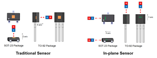
Figure 1: Comparing Direction of Sensitivity of Traditional and In-plane Sensors
Before discussing the benefits of an in-plane Hall switch, we’ll quickly cover the different market terminologies used for this device to avoid any confusion. In-plane Hall-effect switches can also be referred to as vertical Hall-effect switches or lateral Hall-effect switches. The term vertical comes from the vertical Hall sensing element within the device, and similar to planar or in-plane, lateral refers to the ability to detect magnetic fields that come from the side of the package.
Now getting back to the advantages of a planar Hall switch. For systems with limited spacing, the device package and/or the direction the magnet approaches the sensor become important factors to consider for design. Lateral sensors can aid in overcoming mechanical limitations by allowing the magnet to approach the SOT-23 or TO-92 packages from directions not supported by the traditional sensors. Not only does this increase placement options, it can also reduce size and save overall system cost. The TMAG5123 is TI’s first in-plane Hall-effect switch with high precision and a wide operating voltage range from 2.5V to 38V.
With the ability to detect parallel magnetic fields, Hall sensors can now be used in place of other technologies. Some of the most common technologies seen in this space are mechanical switches, xMR devices, and reed switches. For more information about vertical Hall-effect switches and how they compare to other technologies, read the following application brief.
As mentioned before, Hall-effect switches can be used in just about any application for proximity detection and the axis of sensitivity is just one of many features to consider. Check out TI’s portfolio of Hall-effect switches for our latest releases and the different features we offer.
Part Number: TMAG5123
Hall-effect sensors in refrigerators
As with most home appliances, over time refrigerators & freezers have evolved into electronic-intensive products. Among many other innovations such as electronic displays, Alexa-enabled WiFi, and highly efficient motor designs, refrigeration systems have many sophisticated sensors to inform the on-board MCU of the inner workings of the system. In this E2E post I will discuss three separate position sensor applications – door open/close, ice dispenser levers, and push buttons.
Door/compartment open & close detection
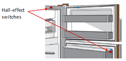
Mechanical and reed switches have predominantly been used in the detection of the opening & closing of the doors to control the light inside the refrigerator. These technologies have been in use for a long time but innovative companies typically make the move to better, more precise technologies first and the rest will follow. Hall-effect sensors with high sensitivity and precisely controlled hysteresis have proven to be most beneficial in this application. The table below details some of the advantages over the conventional technologies.
|
Specification |
Hall-effect switch |
Reed switch |
Mechanical switch |
System-level Benefit |
|
Magnet orientation |
Orthogonal or parallel |
Parallel |
N/A |
Hall-effect switches have options that offer greater flexibility in placing the magnet in relation to the sensor (in-plane and orthogonal). Mechanical switches do not need magnets. |
|
Current consumption during Standby |
µA to mA range (but can be in the nA range if powered down) |
Zero |
Zero |
For mains powered applications, µA to mA range is typically good enough. |
|
Polarity sensitivity |
None (omnipolar switch) |
None |
N/A |
Omnipolar switches will respond to either magnet polarity. |
|
Switch loads directly? |
Requires added circuitry |
Yes (up to single-digit amps) |
Yes |
Reed and mechanical switches essentially close the current path to the light bulb directly. |
|
Response time |
~10 µs (high-bandwidth devices) ms range (low frequency, duty-cycled devices) |
25 to 100 µs |
Immediate |
High-bandwidth Hall-effect switches are very fast. Have not tested mechanical switches, but they should be very fast as well. |
|
Life expectancy |
Effectively unlimited operations – limited by silicon life expectancy |
Up to 1 billion operations |
Limited by wear and tear of contact |
This is a major drawback of mechanical switches. |
|
Hysteresis |
Single-digit mT range |
40% - 90% variation |
None (but open/close location may vary over time to wear and tear) |
Consistent open/close location detection achieved with Hall-effect switches. |
|
Assembly |
Standard PCB assembly |
Manual board assembly |
N/A |
Reed switches experience high yield loss due to being brittle. |
|
Operating temperature |
-40°C to 125°C |
-55°C to 200°C |
Wide range |
All technologies are sufficient since room temp is essentially needed. |
|
Price |
Prices are comparable. |
All technologies should be considered for their technical merits and not pricing alone. |
||
As is summarized in the table, the main drawback to using Reed switches is the yield loss during assembly, and for a mechanical switch it is the lifetime of the product due to wear and tear. Mechanical switches are also visible in the door frame and are simply not aesthetically pleasing. In contrast, the Hall-effect switch’s main benefits are the life expectancy because of its contactless behavior and also getting consistent results in the opening & closing of the refrigerator doors, which is very important for companies that want that user experience.
Two exceptional Hall-effect switches are the DRV5032 and TMAG5123 (with in-plane sensing capability).
Ice dispenser lever and push buttons
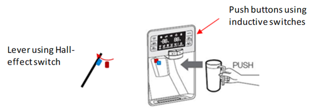
Similar to the open & close detection of a refrigerator door, a Hall-effect switch performs the same function of detecting the presence or absence of a magnet. Consistent results can easily be achieved, and manufacturing procedures do not have to include a specific orientation of a magnet by using an omnipolar switch that responds to both north and south magnetic fields.
The LDC family of inductance to digital converters are signal conditioning ICs that measure the change in resonance of a inductive coil laid out on a PCB when a conductive target approaches or moves away from the coil. These sensors can be used to measure minute deflections in the conductive material as a button touch or as a precise linear sensor for proximity sensing.
Some of the key benefits of touch buttons, sliders or knobs implemented using inductive sensors are:
Get started with TI’s inductive sensors
No matter what type of user interface or HMI you are designing, TI has the right inductive sensor for your design – the LDC3114-Q1, an automotive 4-channel inductance to digital converter for low-power proximity & touch-button sensing.
Additional Resources
Part Number: IWR6843
Hello,
There is an issue with the rangeproc header files used in the objectdetectionandtracking DPC. It erroneously links to the header files for the rangeproc from the toolbox. If you update the #include at the top of objdetrangehwa.c (line 60) and objdetrangehwa.h (line 150) [path is "C:\ti\mmwave_industrial_toolbox_4_9_0\labs\common\src\dpc\objectdetectionandtracking\objdetrangehwa"] to be the following:
#include <ti/datapath/dpu/rangeproc/rangeprochwa.h>
the lab should compile and run normally. The issue affects the below demos:
This will be fixed in the next version of the toolbox release. Alternatively, ITB version 4.8.0 will work until the next toolbox update is released.
This FAQ discusses the Memory Architecture and Allocation of Applications implemented on programmable mmWave sensors.
Programmable mmWave sensors include an ARM core (MSS) and one or both of following processing engines: Hardware Accelerator (HWA) and DSP (DSS).
For Gen1 mmWave sensors the DSP is a C647x, for Gen2 devices the DSP is part of the C66 family.
Following documents include detailed information about the C647x and C66x memory subsystems:
For C647x:
C64x+ Megamodule User Guide
https://www.ti.com/lit/ug/spru871k/spru871k.pdf
For C66
TMS320C66x DSP CorePac
https://www.ti.com/lit/ug/sprugw0c/sprugw0c.pdf
mmWave Sensors usually include following memories:
In a mmWave Application, the radar processing is usually implemented on the HWA or the DSS.
Memory Allocation for Processing using the HWA
For processing data with the HWA the dedicated Input/Output buffers must be used. There is no alternative.
To optimize processing input data is organized in PING/PONG buffers. The optimization is due to the fact that processing of the PING buffer happens when the PONG data is transferred by the EDMA. So, there are no additional delays cause by the EDMA transfer of the data. Of course, this optimization requires 2x memory buffers.
A nice example of this type of processing is provided in the mmWave SDK demo documentation for Doppler FFT. See DopplerProcHWA
Doppler DPU
Memory Allocation for Processing using the DSP
When processing data with the DSP, first it is required to have highly optimized implementations of the most cycle intensive algorithms. For best performance fixed point algorithms are desired. If there is need for more precision floating point format may be needed. The DSPs available in the mmWave sensors support both fixed point and floating point data formats. In order for these implementations to provide best performance they have to run from fastest Program and Data memories: L1P and L1D.
Since both memories L1P and L1D can be configured part memory and part cache, the application developer will have the choice to
When part of the L1D will be used as memory, the application must allocate in this memory the input and output buffers for the most cycle intensive algorithms. The buffers would be overlayed for each processing stage.
Here is an example from the mmwave SDK 2.1 demo:
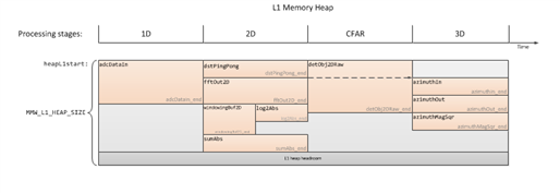
Data would be transferred to and from the L1D buffers using the EDMA. Usually the output results are transferred to L3 memory.
Part Number: AWR1843AOP
It was identified that the mmWave SDK 3.5.0.4 demo for AWR1843AOP provides incorrect elevation z value. The value computed by the demo has incorrect sign. For example, when correct elevation is z = 1m, the demo reports z=-1m.
This issue is due to incorrect Tx antennae numbering used in the demo.
In order to correct this issue please modify the following file as follows and rebuild the demo binaries as described in the SDK User Guide.
C:\ti\mmwave_sdk_03_05_00_04\packages\ti\board\antenna_geometry.c
Replace
ANTDEF_AntGeometry gAntDef_AWR1843AOP = {
.txAnt = {
{0, 2},
{0, 1},
{0, 0}
},
.rxAnt = {
{3, 0},
{2, 0},
{1, 0},
{0, 0}
}
};
With
ANTDEF_AntGeometry gAntDef_AWR1843AOP = {
.txAnt = {
{0, 0},
{0, 1},
{0, 2}
},
.rxAnt = {
{3, 0},
{2, 0},
{1, 0},
{0, 0}
}
};
