A related question is a question created from another question. When the related question is created, it will be automatically linked to the original question.
If you have a related question, please click the "Ask a related question" button in the top right corner. The newly created question will be automatically linked to this question.
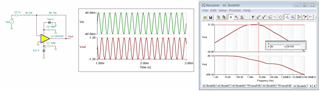
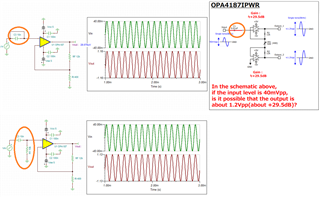
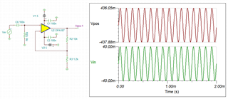
This is the circuit time domain response, where Vout is approx. 260.17mV with circuit gain of -260.17/40 = -6.5V/V.
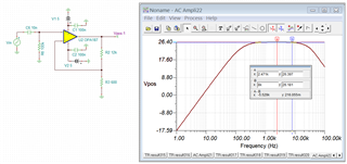
The 10nf capacitor has impedance of 1/sC = 1989.5Ω at 8kHz. Without the capacitor coupling, the gain is -36.36 V/V or 31.21dB. As frequency increases, the circuit gain is increasing because the impedance of capacitor is decreasing. At 8kHz, the gain is at 16.197dB or 6.454 V/V, which agrees with the transient simulation above.
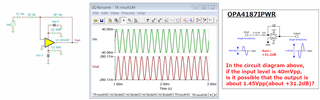
If I understood your inquiry correctly, you want to have Vout at 31.2dB at 8kHz. In this case, you have to reduce the value of capacitive coupling. You may get it close, but it is not quite at 31.22dB. The reason is that OPA187 starts to attenuate the gain at 8kHz already. If you want to achieve 31.22dB exactly, you have to get a slightly higher BW op amp under the same configuration.
Enclosed is the above simulation. If you have additional questions, please let us know.
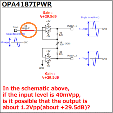
I designed the PCB of schematic OPA4187IWR_2. Now U1 and U2 are ADA4522-4ARUZ. However, the PCB does not have good temperature characteristics. So I want to improve temperature characteristics by replacing U1 and U2 with OPA4187IPWR. However, gains would be kept as they are. So, I'm keeping a close eye on Gain.
The blue curve of closed loop gain plot in figure 7 of datasheet does not show the highest possible gain, but only the frequency response when you set a gain of 20dB. You can see that with a set gain of 20dB the frequency response is linear up to about 30kHz. Of course, higher gains than 20dB are possible, but not for frequencies above 30kHz.
The poor temperature characteristic you observe is a direct consequence of not having sufficient gain reserve. You need a minimum gain reserve of about 20dB, better more. So if your OPAmp has a maximum gain of 30dB at the frequency of interest, or by other words, if it has an "open loop gain" of 30dB at this frequency, the maximum gain you can set should be below 10dB.
Having a gain reserve of 20dB is the absolute minimum. For a precision application you will need way more gain reserve. Then a gain reserve of 40dB is a good choice.
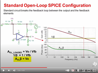
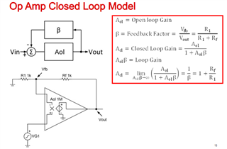
Loop Gain T is defined as T= Aol/Acl. If you take log on both end of the equation, where logT = log(Aol) - Log(Acl). In a closed loop op amp feedback circuit, Acl = Aol/(1+T), where T=Aol/Acl = Aol*β, where β or Beta is β = Vfb/Vout or 1/β = Vout/Vfb = Acl. There are many ways to express the following relationships and do not get confused with different forms of Open and Closed Loop Expression. The various Open and Closed Loop math expressions can all be derived from the slide below.
There are some issue with you draw your schematic. You need to place the DC bias at the input of inverting op amp. The circuit won't work as you drew in the pdf inquiry.
If you have to use OPA4187, adapt Kai's suggestions and place the amplification in two op amp gain stages, which it will give you the higher BW for 8kHz input signal that is based on Gain Bandwidth Product Rule. Use simulation tool to help you understand these relationships.
If you have additional questions, please let us know.
How much is the maximum gain in the left schematic?
Before I reply to you inquiry tomorrow, what options do you have to increase the input amplitude.
Question-1:
Currently, the input is 40mVpk. Do you have a change to increase the input voltage swing, say 50-60mVpk at 8kHz, ?
Question-2:
What types of load that Output1 and Output2 are driving? The output is a differential output or the load is Output1 - Output2.
Question-3:
Output signals have a slight phase shift from input signal as it is configured. Are you concerned about the phase shift? I assumed that it is important to have the voltage swing amplitudes of the 8kHz at the output.
Kai has provided a better solution, but your PCB is already made and you are unable to adapt it (if I understood your scenario correctly).
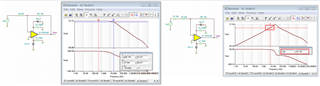
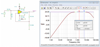
Alternatively, you have to lower the gains of the circuit. You need to configure the OPA187 to approx. 21V/V or lower. As it is configured, there is approx. 0.8% attenuation at 8kHz in the simulation below.
If you lower the gain to approx. 15-16V/V, see the figure below, the attenuation figure is lowered to approx. 0.45% at 8kHz. I am unable to comment on it, since I do not know your accuracy requirements. You should check with the simulation. Normally, you may need to go up at least 10dB from your desired gains to have the margin within a given frequency.
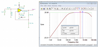
It looks acceptable, but I do not know your error or design requirements. The 20dB is equivalent to 10 V/V. At gain of 11V/V, the gain error is approx. 100% *(20.801-20.765)/20.801 = 0.173% (dB gain error)
In terms of input signals, 40mVpk will have gains of 11V/V on the top amplifier (lower one is -10V/V). 40mVpk --> 0.43864Vpk at approx. 4kHz (no attenuation).
40mVpk --> 0.4368Vpk at 8kHz. The output voltage swing %error is approx. 0.43%.
C6 and R6 (10nf and 100k), high pass filter has some insignificant errors. If you increase the high pass capacitor from 10nf to 100nf, You may increase the output voltage swing by 2mVpk or so in range.
What are you going to do with the integrator? Your input signal is 8kHz in sinewave. If you integrate the input signal at 8kHz, you will get back in cosine signal. As it is configured, the integrator is only able to integrate low frequency signal. Please let us know what you are trying to do.
Because of not having enough gain reserve, you would not only observe an earlier fall in the frequency response but also suffer from a higher temperature drift of gain.