This thread has been locked.

If you have a related question, please click the "Ask a related question" button in the top right corner. The newly created question will be automatically linked to this question.

AMC1200-Q1: Current Sensing

Part Number: AMC1200-Q1
Other Parts Discussed in Thread: AMC1200, AMC3301, AMC1200EVM

Hi,

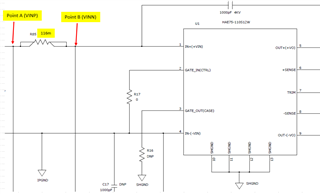
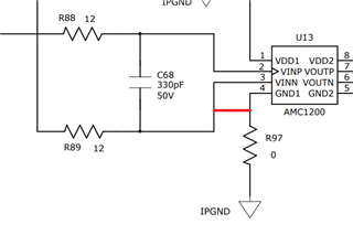
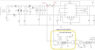
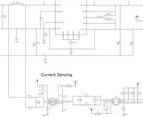
I use AMC1200 to do current sensing in my design below,

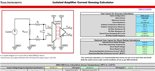
The reference circuit i use was based on below isolated amplifier current sensing tables.

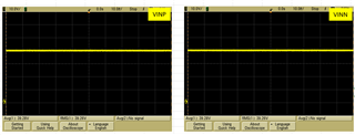
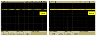
However even the input voltage is different (50Vdc or 60Vdc, i always get the same output level for VoutP or VoutN.

VDD1 & VDD2 both supply with 5V.
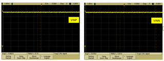
Vin (V) VINP(V) VINN(V) VOUTP(V) VOUTN(V)
50 5.7 5.7 2.48 2.478
60 5.657 5.663 2.496 2.48

I upload my schematic design for your reference.

Please help to confirm my design is it mistake in schematic?

Why the output remains unchange even input power change?

Thank you.

Best regards,

Ku

AMC1200 Current Sensing design.xls

  • Hi Ku,

    The device cannot sense input voltages that are higher than the supply voltage as per the common-mode input specifications. 

    You may need to re-design the high side supply or consider moving to AMC3301, a device with an integrated DC/DC converter. 

    When the device is not populated, is there a measurable voltage across the shunt? 

  • Hi Smith,

    When the device is not populated, is there a measurable voltage across the shunt? 

    -i think no. Cause by measure the waveform of VINP & VINN pin, value of both pin are same.

    Is it my current sensing design of AMC1200 was wrong? 

    That why can't get any voltage reading across the shunt.

    Just by change the device from AMC1200 to AMC3301, my current sensing circuit will be working?

    For your information, my input power range is Vdc = 46V to 160V, nominal operation is 110V. Max current 1.8A.

    Best regards,

    Ku

    SCH-1096-00_Current Sensing AMC1200.pdfSCH-1096-00_Current Sensing AMC3301.pdf

  • Hi Ku,

    Is current flowing in the system? If so - then there should be a measurable voltage across the shunt. 

    How is the high side supply generated? It is not shown on the schematic. If the high side supply is the issue, then switching to the AMC3301 may help. 

    I recommend tying VINN to GND1 in order to ensure that the inputs are within the input common-mode range. 

  • Hi Smith,

    Actually i use AMC1200EVM board to test my current sensing circuit.

    I connect the AMC1200EVM board J2 pin 1 to Rshunt point A and J2 pin 2 to Rshunt point B.

    Rshunt value i use 116.mOhm. AMC1200EVM board VDD1 and VDD2 i supply by 2 external power supply 5V.

    AMC1200EVM board VDD1 GND is connected to my circuit IPGND.

    SCH-1096-00_Current Sensing AMC1200EVM.pdf

    Is current flowing in the system? If so - then there should be a measurable voltage across the shunt.

    -I think there is current flow through because it was my system power input supply.

     My system was able to power on and working with above design.

     Just my current sensing circuit design can't work.

    Attach AMC1200EVM VINP/N & VOUTP/N waveform for your reference.


    Per your previous info, because my input voltage (VINP & VINN) higher than supply voltage(VDD1) so AMC1200 cannot sense the Rshunt voltage?

    So i need to change AMC1200 to AMC3301 device for my current sensing circuit?

    Thank you

    Best regards,

    Ku


  • Hi Smith,

    I recommend tying VINN to GND1 in order to ensure that the inputs are within the input common-mode range.

    -I try before connect GND1 to point in front R89, this cause Rshunt & AMC1200 ic brunt.

     So is it OK to connect VINN to GND1?

    Thank you.

    Best regards,

    Ku


  • Hi Ku,

    During these tests, how was the high side supply 5V generated? 

    The transformer on the EVM?

    If so, you should be able to connect VINN to GND1 as the high side supply can float. 

    What is the power dissipation rating of the shunt resistor you are using? 

    At least 1W?

  • Hi Smith,

    I tested it by the circuit i built on my 1096 PCBA, not through AMC1200EVM board because i not yet receive the AMC1200EVM board that moment.

    So the high side 5V i modified my 1096 circuit to use external DC power supply to provide 5V to VDD1.

    The circuit was as attached schematic below.

    SCH-1096-00_Current Sensing AMC1200_ 01122023.pdf

    The Rshunt power rating was 1W.

    Thank you.

    Best regards,

    Ku