Part Number: DS90UB941AS-Q1
Other Parts Discussed in Thread: ALP, USB2ANY
Hi team:
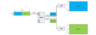
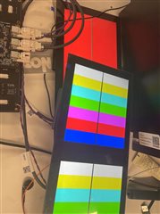
I used the 941AS splitter mode but could not output the picture. Besides, I try config SA8155 output 1920x720 or 960x720 size image ,and config ub941 work in single FPD-LINK Transmitter mode, Panel0 can display image
More Info:
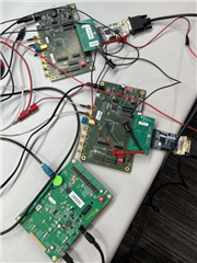
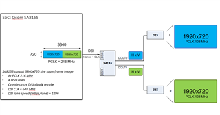
1. Host SoC: Qcom SA8155
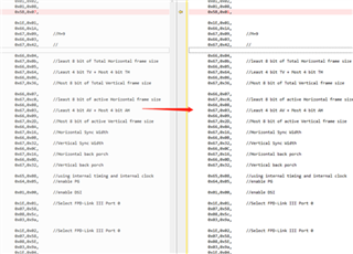
2. Host Soc output timing info:
1920*720@60
uVisWidth = '1920'
uHsyncFrontPorch = '50'
uHsyncWidth = '50'
uHsyncBackPorch = '50'
uVisHeight = '720'
uVsyncFrontPorch = '50'
uVsyncWidth = '50'
uVsyncBackPorch = '50'
uPixelFreqInHz = '108054000'
960*720@60
uVisWidth = '960'
uHsyncFrontPorch = '25'
uHsyncWidth = '25'
uHsyncBackPorch = '25'
uVisHeight = '720'
uVsyncFrontPorch = '50'
uVsyncWidth = '50'
uVsyncBackPorch = '50'
uPixelFreqInHz = '54027000'
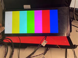
3. config SA8155 output 1920x720 or 960x720 size image ,and config ub941 work in single FPD-LINK Transmitter mode, Panel0 can display image
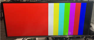
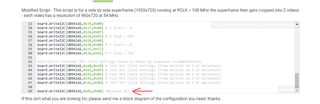
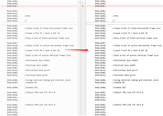
4. config SA8155 output 1920x720 size image ,and config ub941 work in attern Generator, set 0x65 = 0xc,Panel0 can display image
5. config SA8155 output 1920x720 size image ,and config ub941 work in attern Generator, set 0x65 = 0x8,Panel0 can not display image
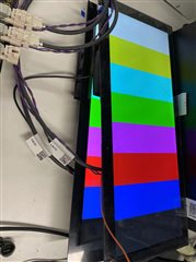
6. config SA8155 output 1920x720 size image ,and config ub941 work in attern Generator, set 0x65 = 0x8; 0x5b = 0x1,Panel0 can display image
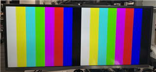
Could you please help to check when i would like to use Symmetric Splitting - left/right setting, what configuration should be set to 941AS to successfully output the SoC picture?
Thanks!