Part Number: DS90UB947-Q1
Hi team,
My customer want to confirm with team if MAPSEL=0 is for JEIDA mapping format.
because they could get attached test result when they follow datasheet information.
OLDI mapping test result of 947.pptx
so their conclusion is MAPSEL=0 is for JEIDA not for VESA so that datasheet information has typo.
could you pls help answer this??
Thanks
Part Number: DS90UB913A-Q1
Hi Team
My customer is considering to use 913 and 964.
they want to know if 913/964 can support BT 601 format 1280x720@30fps with YUV 422 8bit.
I think it is not a problem but I want to check with team 1more time for sure.
Could you pls help make sure this??
and 1 more question is
our DES use fixed CSI output BW. so that after send all data, rest of time before get next line data would be blank with LP11.
so my understanding as below timing diagram is correct??
this is line level diagram. so 1-1 is 1st camera/1st line, 1-2 is 1st camera/2nd line.
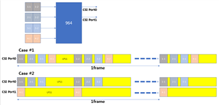
Thanks for your support as always~!!
Part Number: DS90UB947-Q1
Hi Team
My customer is developing 947 <->948 for CID application.
now they met some issue that
when they test 947 with their tester display module with 948, 0x0c bit[0] is high and display is OK.
but when they test 947 with customer display module with 948 0x0c bit[0] is low and display also OK. and customer cannot access to DES via BCC.
As I experienced from 949, if Link detect status is failed, HDMI Input port was not enabled. so display was NG.
Does device enable OLDI port input even Link detect status (0x0c bit[0]=1b'0 ) is low?? so this doesn't care Link detect status for outputting data on Link channel??
Thanks~
Part Number: DS90UB947-Q1
Hi Team
My Customer is asking how much tolerance 947device has for Mode_sel.
now my customer wants to set #5 for mode_sel1
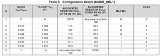
but they only has 82Kohm PU/100Kohm PD. so ratio would be 0.549. but recommended ratio is 0.560.
so customer is asking if their configuration is OK.
Could you pls help answer this to customer??
Thanks
How do I debug DP Alt Mode issue over the USB Type-C interface?
Part Number: TPS65988
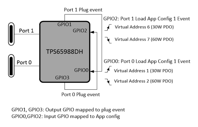
This example project has been developed to help designers who are working on dual port applications such as smart plugs, multi-port adapters, avionics seat backs, wall-sockets... which often require dynamic power sharing between ports. The highly configurable TPS65988 can implement dynamic power sharing without using an EC in the design. The simple to use GPIO App configuration event feature in TPS65988 makes this stand-alone solution possible.
The figure pictorially shows the control logic used for power sharing. In this example, lets assume that the total power available to the system is 60W. When no ports are connected, the total power available shall be delivered to the first device, getting connected to either of the ports. When the second device gets connected, the total power shall be split equally between the two ports.
The App Config events in the project file are configured to load PDOs in Transmit Source Capabilities register (0x32) dynamically (based on plug event) and execute SSrC PD message task (PD Send Source Capabilities). App Config input events are mapped to GPIO0 and GPIO2. App Config input GPIOs are connected to output plug event of the other port (GPIO1 and GPIO3). The plug event GPIO of a port will go high when the port makes connection, this will trigger App Config GPIO of the other port to scale down its power to half (Virtual address 6 and 1). Similarly, an unplug event will cause the other port to advertise full power (60W)
This project can be tested using TPS65988EVM. To know more about the application, please go through TPS65988DH: Integrated Type-C PD Dual-Port Wall Socket With Power Balancing.
Part Number: TUSB9261
Where can I get the latest VIF file for the TUSB9261 KGD for USB-IF Compliance Testing?
Part Number: TUSB8041
When using the TUSB8041, does it matter which power supply ramps first and how does it impact power on reset timing?
Part Number: SN65DSI84
The video on my display panel is flickering when I use these devices. How do I debug this issue?
Part Number: DP83TD510E
FAQ – Does my DP83TD510E need to be initialized to establish link?
The DP83TD510E is a 10Base-T1L PHY that can link between devices up to over 2km of SPE cable. TI’s preproduction samples require an initialization script to tune the device to establish link, while the released device eliminates the need for register configuration before link-up is ready.
Which revision of silicon do I have and is initialization required?
The revision of silicon can be found in MII_Reg_3, address 0x03 with the following legend:
|
Silicon |
Register MII_REG_3 (0x0003) |
Initialization Required |
|
Engineering Samples |
0x0180 |
Yes |
|
Final Production |
0x0181 |
No |
What are the initialization registers for Engineering Samples?
When auto-negotiation is enabled, the DP83TD510E will resolve the Master/Slave relationship as well as output operating mode with it’s link partner without needing to be set by the designer. Forced modes can be used by designers to fix the Master/Slave setting of the PHY as well as output operating mode on both sides of the link.
The initialization scripts for Auto-negotiation as well as Forced Master/Slave and output operating mode can be found attached below:
/cfs-file/__key/communityserver-discussions-components-files/138/3566.AutoNegotiation_5F00_Init.txt
Can I use the on-board MSP430F5529 to program the PHY to initialize on start-up?
Yes! The MSP430F5529 controller can be flashed with firmware that will program the necessary registers on silicon that requires initialization. Please note, that it is not necessary to flash this firmware on production silicon as it will treat each DP83TD510E device the same. You can use the DP83TD510E-EVM-Driver.txt to flash the self-initializing firmware on EVM's with the sample silicon.
2553.DP83TD510E-EVM-Driver.txt
Can I find a description of each register in the initialization script?
The registers set in the initialization script are used to tune the internal digital and analog blocks of the PHY for establishing over the channel. These will not be included in the datasheet. The production silicon sets the default register values so that no tuning is needed and the PHY will establish link on start-up.
