This thread has been locked.

If you have a related question, please click the "Ask a related question" button in the top right corner. The newly created question will be automatically linked to this question.

IWR6843ISK-ODS: can’t able to Flash Binary using the CCS debug with mmwaveboost board

Part Number: IWR6843ISK-ODS
Other Parts Discussed in Thread: UNIFLASH, MMWAVE-SDK, IWR6843, MMWAVEICBOOST, IWRL6432

Hi team,

Our customer was requesting assistance:

System Configuration

  • Windows 11,
  • CCS Studio Version :- Latest 12.2.0 (tried v8.0 and v10 as well)
  • Uniflash Version 8.1.1
  • MMWAVE-SDK Version 3.05.x.x
  • Radar Board : IWR6843-ISK-ODS
  • BoostBoard : MMWAVE BOOST

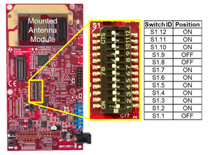
I’m able to flash the IWR6843-ISK-ODS (radar board) individually, but When I Connect IWR6843-ISK-ODS Board With MMWAVEBOOST and Configure it as a Flashing mode through jumper Settings. it failed, I'm trying to flash a binary image to the board but it shows an error. Below I have provided more details.Below image I have configured the DIP Switch which show in below image 
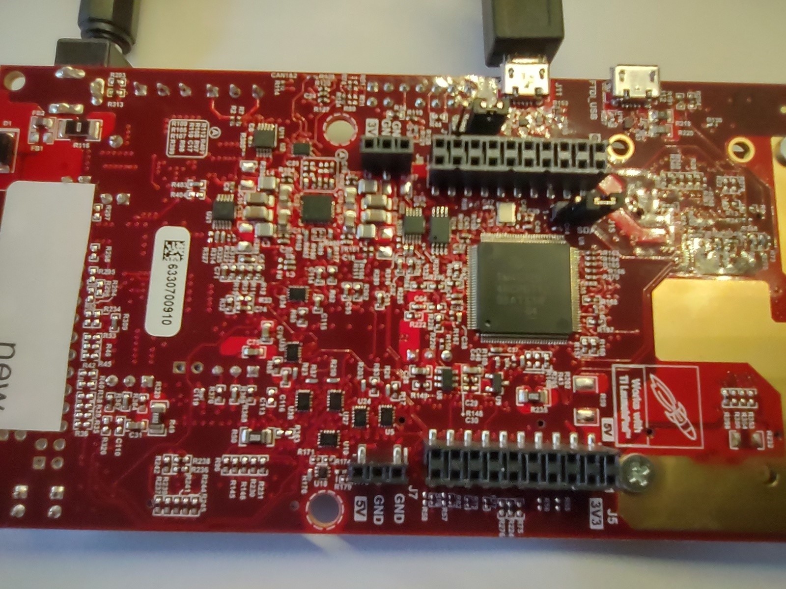
Below is the configuration I have Done

Board:- IWR6843-ISK-ODS

Debugger :- Texas Instrument XDS110 USB Debug Probe

 -> XDS Configuration Detail
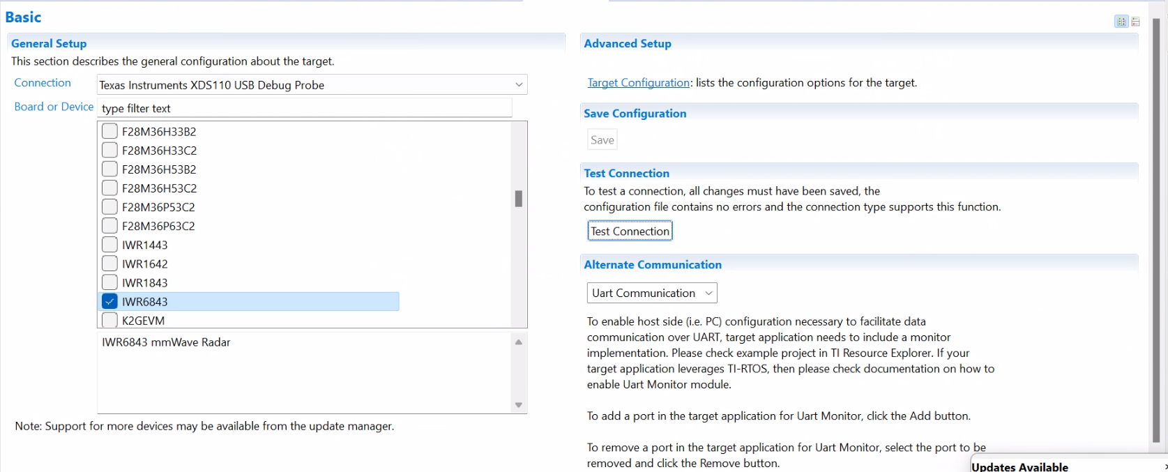
 -> XDS Configuration Detail

-> When Click on Test Connection, It shows an Error Below I have Provided The Logs

This utility will attempt to reset the controller.
This utility has successfully reset the controller.

-----[Print the reset-command hardware log-file]-----------------------------

The scan-path will be reset by toggling the JTAG TRST signal.
The controller is the XDS110 with USB interface.
The link from controller to target is direct (without cable).
The software is configured for XDS110 features.
The controller cannot monitor the value on the EMU[0] pin.
The controller cannot monitor the value on the EMU[1] pin.
The controller cannot control the timing on output pins.
The controller cannot control the timing on input pins.
The scan-path link-delay has been set to exactly '0' (0x0000).

-----[An error has occurred and this utility has aborted]--------------------

This error is generated by TI's USCIF driver or utilities.

The value is '-233' (0xffffff17).
The title is 'SC_ERR_PATH_BROKEN'.

The explanation is:
The JTAG IR and DR scan-paths cannot circulate bits, they may be broken.
An attempt to scan the JTAG scan-path has failed.
The target's JTAG scan-path appears to be broken
with a stuck-at-ones or stuck-at-zero fault.

[End: Texas Instruments XDS110 USB Debug Probe_0]

  • I have changed target configuration With Other Option(SWD/cJTAG) but it failed.

  • I Have Go through the link Provided by the TI Recommendation

          Strategy for debugging JTAG connectivity problems

  • I follow the All Procedure but was not able to update the new binary firmware on the IWR6843-ISK-ODS with MMWAVE BOOST.

Method 1:- Connect the MMWAVEBOOST and IWR6843 Radar Board  And Try to flash with CCS Debug it shows the Same Error -2131

Method 2:- Try to Flash binary with the UNIFLASH software but it's not able to upload And through the error. below I have attached the image

Method 3:

->  Flash the  IWR-6843-ISK-ODS Radar board with CCS-Debug binary for specific CCS-Studio Debugging.

-> config DIP-Switch IWR-6843-ISK-ODS Radar board, and attach  the MMWAVBOOST  board, and try to flash with CCS Studio and UNIFLASH flasher As well.


Can you please suggest solution on this that will really help us to move forward on the project

  • Is there Any Configuration missing in the above provided cases?.
  • Im performing any wrong steps?
  • Is Any Hardware Issue?
  • Hello,

    Please refer to the Out of the Box Demo and carefully step through it, following the embedded links to the EVM Setup Guide for your hardware: IWR6843ISK + ICBOOST.

    When you power up the ICBOOST, are LEDs on both the ICBOOST and the ISK board illuminated? Are you pressing the RST button on only the ICBOOST? (When utilizing the ISK + ICBOOST, you should only press the RST button on the ICBOOST, not the ISK's RST button).

    Regards,
    Luke

  • Hi Luke,

    I got the response from the customer:

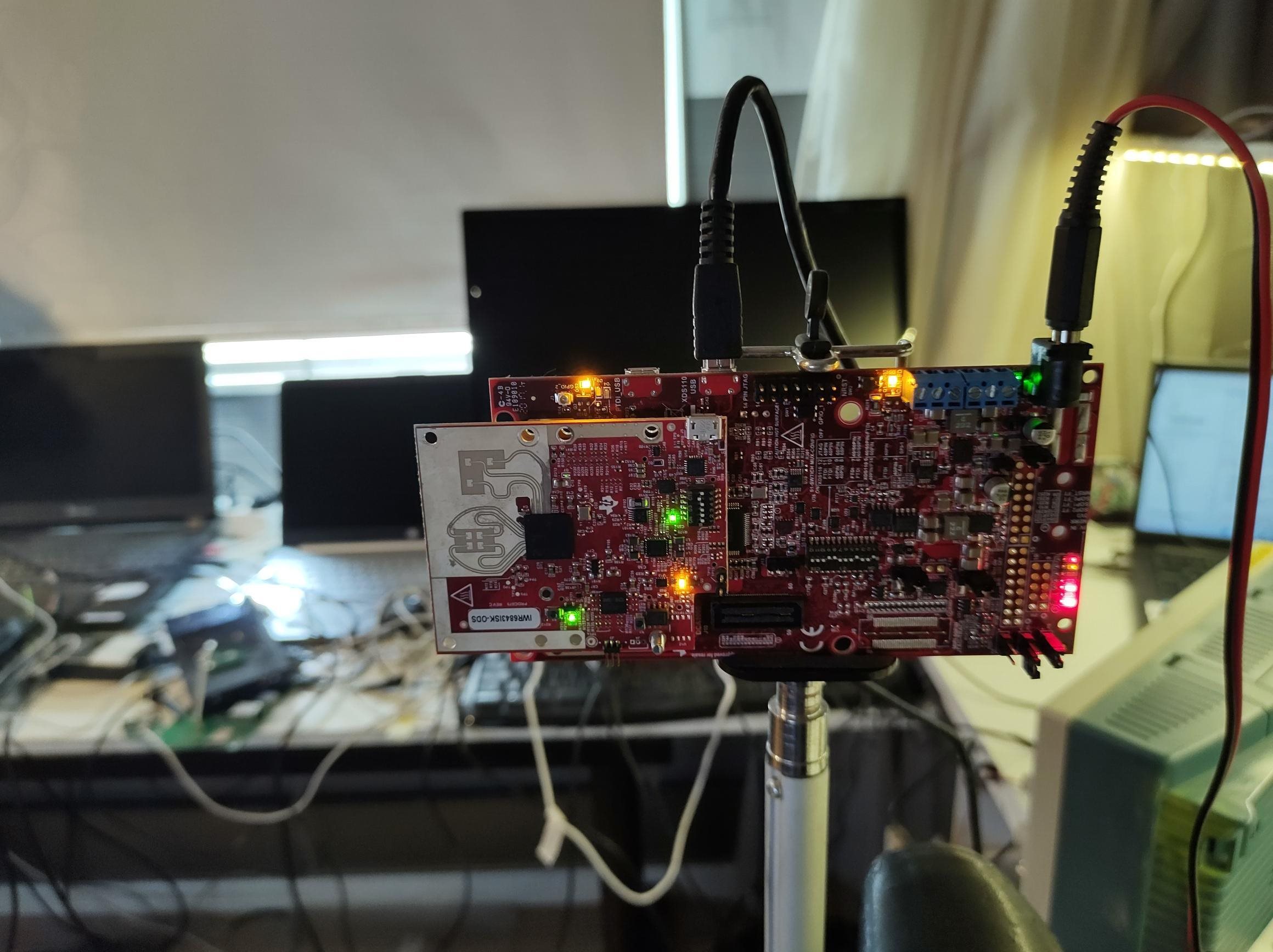
    1: ICBOOST and IWR6843-ISK-ODS board LED are ON (below image attached) and I'm pressing only the ICBOOST reset button

    2: I have tried the OOB 6843-ODS example, as suggest in the solution thread
    Current version: MMWAVE-SDK-3_50_x_x tried to Flash but the same error after some more trials I upgraded the MMWAVE-SDK-3_60_x_x and CCS V12.3 Latest one and see the below error -1170.(below image attached)

    Thanks and Regards
    Akshar Gajjar

  • Hello,

    Can you please ask the customer to try flashing the device with the Desktop version of Uniflash (i.e. download the app rather than using it through CCS or in the cloud)? The issue could be coming from doing this through CCS, which we tend not to do. 

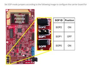
    Also, is the customer trying to use the device in debug mode, or simply trying to flash any binary at all? In either case, to flash a binary to the device, the EVM + ICBOOST must be in flashing mode, which it currently is not in the most recent image you sent but was in the original set of pictures. SOP0 and SOP2 should be jumped for flashing mode. Please refer to the EVM Setup Operational Modes guide.

    With the software versions listed, there should be no problems. I again recommend following the Out of the Box Demo, but this time using Uniflash as I've mentioned above. If this still doesn't work, please ask your customer to more thoroughly walk me through their step-by-step process they are following.

    Regards,
    Luke

  • Hi Luke,

    I got the response from the customer:

    thank your quick reply. for the wrong SOP configuration image, i have shared that for the LED Indication purpose. we are following the first thread image sequence(already shared in today's document).

    i have tried to Flash with the uniflash but was not able to flash. uniflash software looks like COMPORT initiates the sequence but ICBOOST is Not initiating any sequence. in the document, i have shared the image.

    All detail of steps I have attached in the document.
    TI-MMWAVE BOOST Step Guide .docx

    thanks and regards
    Akshar Gajjar

  • Hello Akshar,

    Thank you for sending me your steps, that will help me clear up some conflusion.

    1. I see that you are flashing the EVM in standalone mode (i.e. by itself, no ICBOOST), then attaching the ICBOOST. This is not necessary! You can flash the EVM with it directly attached to the ICBOOST. Follow the instructions in the section ISK Style With mmWaveICBoost Attached in the EVM Setup Operational Modes Guide. This should make the process easier for you. Basically, once you've set the switches right on both boards, all you have to do is switch the SOP jumper on the ICBOOST to switch between the two modes and you do NOT have to flip any switches. It is much more concise. 

    2. When you have just the ICBOOST alone connected to your PC, there should be no COM ports because the ICBOOST is just a carrier/expansion board for the radar device. For the COM ports to show, the device needs to be connected to the PC either (a) directly in standalone mode or (b) indirectly by being mounted to the ICBOOST which is connected to the PC. So the behavior you listed at the bottom is to be expected.

    3. Unfortunately, debugging our devices is not (currently) as easy as clicking the debug button as is the case with our microprocessors and other TI devices. You must follow the steps in this guide: Using CCS Debug. 

    If you take into account those points, you should no longer run into your flashing issues, and you should be able to use CCS Debug mode successfully.

    Hope this helps,
    Luke

  • Hi Luke,

    as you suggest now I'm not removing the ISK-ODS board, setting the dipswitch configuration, and trying to Flash with uniflash software, unfortunately, it's getting the same error.

    below i have attached the two files with the steps and configuration.
    Flash Steps Guide_R2.pdf
    #2 Flash Stpes Guide.docx

    I have gone through the guide you referred. if the below configuration/steps are different than your steps, can you share your steps with me in the document? that really help me to solve this issue.

    Thank and Regards
    Akshar Gajjar

  • Hi Akshar, 

    All of your steps seem correct in that document. You could omit step 4; you can power on the board with SOP0 and SOP2 jumped, but since in steps 6 & 7 you set the SOP and reset, this is the same. You did not do anything wrong; it is just an unnecessary step.

    Onto debugging. What again is the error you are receiving? Can you send a screenshot of your device manager; what do the COM ports look like at this point? 

    Though it should not matter, try the process with SDA on 1-2 instead of 2-3.

    Report back on the results of this.

    Regards,
    Luke

  • Hi Luke,

    I got the response from the customer:

    here I'm attaching the result as you suggest I have changed the SDA Jumper as you suggest it gets the same error o have provided in the below attachment.
    COM-port and error details .docx

    for your information, I have checked all jumper setting in this document. www.ti.com/.../swru546e.pdf

    and possible jumper setting(like ICBOOST DIPSWITCH and SDA Jumper as well ) I have applied and checked in all cases I see failer,

    is there any different issue? because I have already taken too much time, and the client is very upset with me regarding this issue.

  • Hi Akshar, 

    Since it seems like you are doing everything correctly, yet you are still seeing a COM port error in CCS, I suspect that you have CCS connected to the device at the same time, and it is holding your COM ports such that UniFlash cannot use them to flash the device. For debugging purposes, make sure that you do not have CCS open at the same time as UniFlash, and let me know if this resolves your issue.

    Regards,
    Luke

  • Hi Luke,

    I got the response from the customer:
    thanks for the quick replay, at the time only one software is open whether CCS Studio or Uniflash.
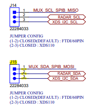
    1: can you confirm the J14 and J15 jumper settings and which one is correct, I have provided the detail in the document.
    2: can we send back the board to TI Lab for Verification board is working or not? if yes what is the procedure.

  • Hello,

    (1) To confirm the J14 & J15 settings, the defaults are fine, 1-2 should be jumped on both.

    What are the specs of your barrel jack power supply for the ICBOOST? If this is not correct, you may be running into issues again.

    Can you please confirm whether or not you were ever able to flash the device in standalone mode without the ICBOOST?

    (2) You can contact your representative or customer support and point to this thread if you believe the board to be faulty.

    Regards,
    Luke

  • Hi Luke,

    I got the response from the customer:
    1: We are using Power supply 5V-3A 2.1mm Barrel Jack.
    2: case 1: I'm able to flash ISK-ODS board in standalone mode (Without ICBOOST). (software : uniflash)
    case 2 : when i follow the EVM Guide WIth ICBOOST. we see the error/failer.

  • Hello,

    In this case, if the customer wants to debug/develop on the device, in the meantime I would recommend the following:

    (1) Flash the ISK with the debug binary (ISK switches set for standalone flashing mode)

    (2) Attach the ISK to the ICBOOST (ISK switches set for ICBOOST/carrier board operation and ensure ICBOOST switches and SOP are set for functional mode)

    (3) Follow the Developer's Guide Section in the OOB Getting Started Guide to see if you can connect to the device and step through code using the ICBOOST XDS.

    If all of this is successful and the customer is able to debug/develop code, then they will no longer be gated by this issue, and it gives some partial confirmation that the ICBOOST is not damaged.

    Regards,
    Luke

  • Hi Luke,

    I got the response from the customer:

    As you suggest I have Followed the Steps You Can see the Steps ON GUIDE#1Guide#1.docx
    In Guide#1 I Have Flash ISK Board Attached to ICBOOST (functional mode)and try to run demo in the mmWave_Demo_Visualizer(cloud UI option)
    when i Select the COM Port and Click on Connect, Both COM Port(USER and Auxiliary) Shows in the Waiting state and try to connect but it seems not able to connect with the ICBOOST

    After some try I have Done GUIDE#2 steps to run the demoGuide#2.docx
    Disconnect the ICBOOST and Set Functional mode in the ISK-ODS Board, now connecting the mmWave_Demo_Visualizer and select the COM port (CFG and Data Port) , click on the connect now it connects successfully to the COM port (IMAGE Attached).

    It seems When ICBOOST connect Device is not able to connect the COM Port.

  • Hi,

    This indicates to me that there is a switch set incorrectly with the MMWAVEICBOOST. If you need to connect to the visualizer with the MMWAVEICBOOST attached, please send a picture of the switch settings when you connect. Else, it sounds like you can connect in the standalone configuration.

    Best,

    Nate

  • Hi Nathan,

    I got the response from the customer:

    here i have attached two documents with more details steps and a picture configuration if you think this is not the expected configuration, please let me know what exactly is missing or wrong.
    Guide#4.docxGuide#5.docx

    as suggested by Luke we have now flashed the prebuilt binary stand-alone and connected the ICBOOST with ISK_ODS and Try to Run the demo in the visualizer and get the data from the Board, but it seems the ICBOOOST board is not working as expected.

  • Hi,

    On step 4 in your Guide #5 doc, can you try flashing the debug.appimage file here: 

    And then try build a program in CCS and flash the board according to the steps in the CCS guide?

    Your switch configurations look right

    Regards,

    Tim

  • Hi Tim,

    I got the response from the customer:
    Please find attached the steps here provide on GUIDE#6. I have updated the Empty image(With Path you suggested) in ISK-BOOST And Attached the ICBOOST and try to flash binary prebuilt binary(out of the box).
    Guide#6.docx

  • Hi Chong,

    Thanks for providing another document. It looks like the switch configuration for the ICBOOST is incorrect. Please see the diagram below

    Can you also ask the customer to determine which revision of the board they have? Please use the guide here:

    https://dev.ti.com/tirex/explore/node?a=1AslXXD__1.10.00.13&node=A__ALBKnY3Q7CdjJcKFqbMEXg__radar_toolbox__1AslXXD__1.10.00.13

    Regards,

    Tim

  • Hi Tim,

    I got the response from the customer:
    I have tried as you Recommend the ICBOOST Configuration but Result is the same Error i see
    we have marking on Radar Chip Name is 678A

  • Hi,

    Can you confirm with the customer that they are using the empty.debug.appimage when they initially flash the device?

    Please ask them to provide another word document with their exact steps.

    Regards,

    Tim

  • Hi Tim,

    I got the response from the customer:

    In the earlier thread, you suggested the empty. release.appimage, I have to flash in the radar board, here attaching the steps that I followed in GUIDE#7 and GUIDE#8
    Guide#7.docx Guide#8.docx

    In the last thread, you asking an empty. debug.app image flash steps? it's confusing now, can you provide me steps? i will follow that steps.
    what binary I have to flash empty.release.appimage Or empty. debug.appimage?

    Thank and Regards

  • Hi,

    Sorry for some confusion again. I have wrongly assumed the customer was using the IWRL6432. For 6843, they need to use this binary:

    I've attached a guide here.

    The overall process is:

    1. flash the 6843 device in standalone mode. Change switch configurations to work with ICBOOST

    2. mount it to the ICBOOST and connect.

    3. Open up CCS and import the project. Build the project, then follow the CCS debug guide to debug the program.

    Can I ask again, since this thread has gotten quite long... What exactly is the customer trying to accomplish? Do they just want to debug their program in CCS?Guide#6_TI.docx

    Regards,

    Tim

  • Hi Tim,

    I got the response from the customer:

    I have not followed your steps as of now ,when i follow the steps and share the result here,

    we want to debug and develop code on CCS Studio and run our custom application,
    we want to debug the code using the CCS Studio, but some how we are not able to flashboard using the CCS Debug code, so we want to make sure the ICBOOST board is correct(suggested by TI person), that's why we are now trying to flash the prebuilt binary if we get success on that, then we go for CCSDebug method.

    The End goal is to develop the application and are stuck at the very initial steps. at least i want flash the debug binary using ICBOOST, so we move forward on the project.

    can i send you a board can you check it on your end ? its possible for you?

  • Hi, please send my response to the customer:

    Were you able to try the Guide#6_TI.docx that I sent in my previous post?

    These two guides should have all of the information you need:

    https://dev.ti.com/tirex/explore/node?a=1AslXXD__1.10.00.13&node=A__AKZl2I1OiS5ssBNGpidsCQ__radar_toolbox__1AslXXD__1.10.00.13 

    https://dev.ti.com/tirex/explore/content/radar_toolbox_1_00_00_26/docs/hardware_guides/evm_setup_operational_modes.html 

    I can check on having them send us a board.

    Please have them send us another detailed list of instructions on what steps they took and precisely where it is failing.

    Regards,

    Tim

  • Hi Tim,

    I got the response from the customer:

    Please Find attached CCS Debug Steps in Guide#9.docx And Guide#10.docx,
    1:- Standalone board CCS debug successfully flash.
    2:- When i attached the board on ICBOOST and try to flash it failed.

    now i have a doubt might be ICBOOST is not working as expected .thanked for the links we are following the same link you have provided for the steps,can you provide me detail to send the board to TI For verification?

  • Hi,

    Please change the SOP2 switch to OFF in the guides. After that, the customer should be able to debug in CCS.

    Regards,

    Tim

  • Hi Tim,

    I got the response from the customer:

    As you shared picture , i have remove the SOP Jumper, with the change its a same result no positive result ,
    now i want to send back to TI lab for board verification, can you please share the procedure.

    that is really helpful

  • Hi,

    Please contact customer support / customer representative, and they will be able to coordinate with you. You may point them to this thread.

    Regards,

    Tim

  • Hi Tim,

    I have checked with CSC team. They do not have the process or solution to help with customers ship devices back to E2E for checking. Do you have any other methods to help with the customer?

    Regards,

    Chong

  • Hi Chong,

    There is no other method to help ship back the device. You can request a return from the customer service team and perhaps purchase a new board.

    Regards,

    Tim