
Other Parts Discussed in Thread: INA333, XTR111, XTR300, XTR116, DAC8551
Hi all,
The plan is to read a digital sensor and send out 4-20mA signal out.
So I'm using the DAC to convert the digital signal to analogue and trying to use…
Dear XTR and DAC Team,
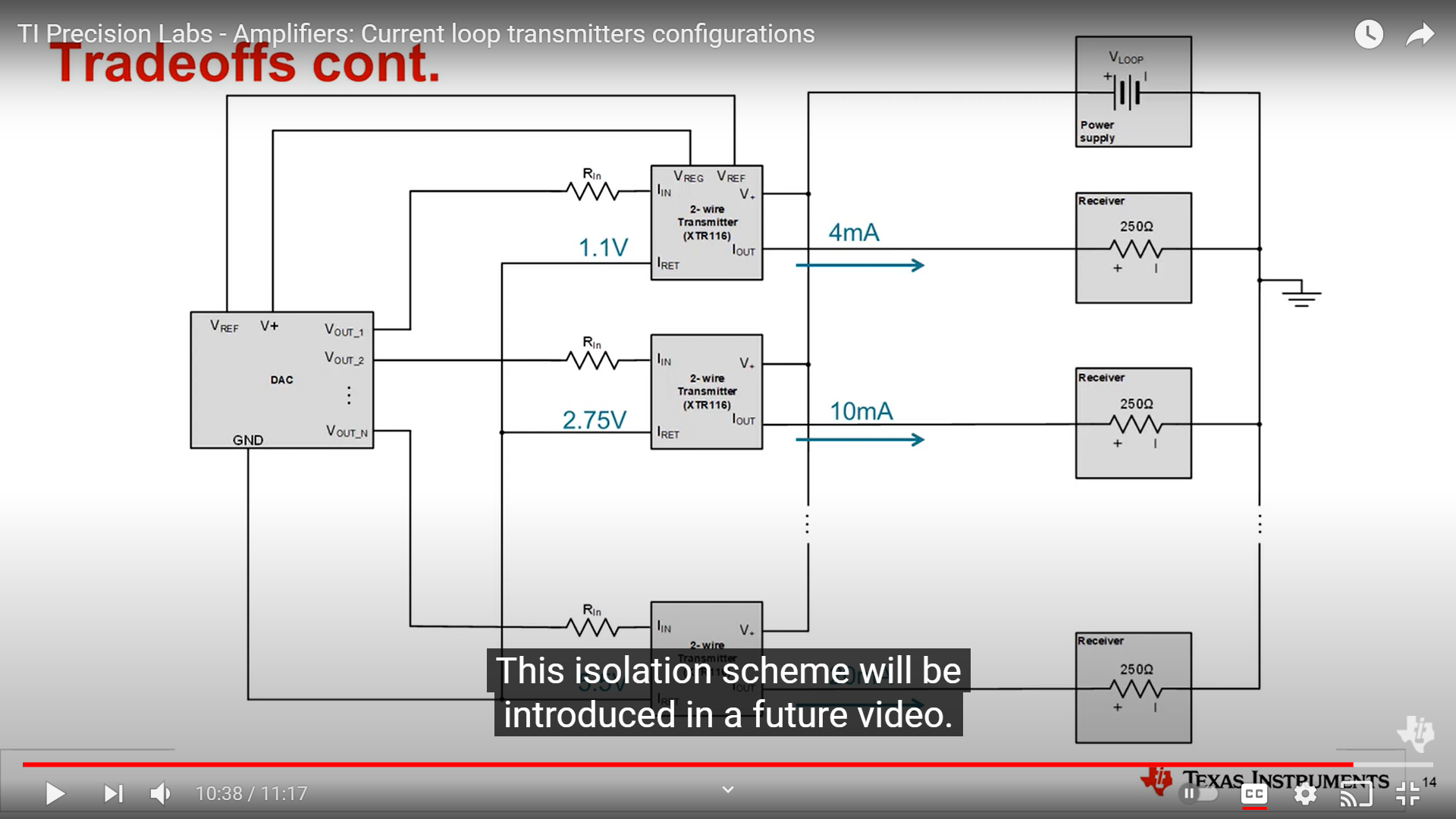
Can you help me with the identification of the Iret pin isolation component for the below details.
Regards
Wasim
XTR116
Problem 1. Can't get full range output only 4-12mA. Input PT1000. Supply 12 to 24 Vdc.
Problem 2. Can't get relay to operate or adjust relay setpoint.
I can send layout, but it can't be public available.
Hello Michael,
Currently, we do not have another product with equivalent functionality to the XTR115/XTR116/XTR117 family of 2-wire current transmitters.
Figure 4 of the datasheet has a basic protection circuit.
A protection scheme for the XTR115/XTR116…
Hello,
The XTR105 is a 2-wire 4mA to 20mA current transmitter incorporating current sources, analog front-end instrumentation amplifier (providing gain) and linearization circuitry intended to interface directly with RTD temperature sensors (without a…
Hello Neel,
-What type of current transmitter is required? 2-wire or 3-wire?
-What type of temperature transducer are you using (RTD, thermistor, thermocouple)?
-Are you referring to an ADC with I2C or SPI interface on the receiver side?
The XTR115, XTR116…
Hello Sumit,
You can add a trimpot to R1+R3 and R4+R5. The R4+R5 resistors divides the voltage output of the DAC into the input current, and the R1+R3 resistors add a 40uA offset to the input current. Both The Vout range of the DAC in the TIPD190 example…
Hi Katlynne,
I tried writing some equations, but when I went back and read your analysis again, it really helped that it was just first-principles of opamps! I agree, the negative feedback will try to drive the voltage difference between the inverting…
Hi Paul,
Can you draw a schematic with what you are proposing. Using this block diagram of the XTR116 as an example (no load connected), the voltage across R1 is seen at the non inverting input of the op amp, and the voltage across R2 is seen at the…
Hi Frank,
The 5V Regulator can only source current approx. 2.5mA or so. What is the output current at 3.3V output? One possibility is that the circuit's load current on Vreg pin exceeds the current limit.

XTR115/XTR116/XTR117 are all 2-wire transmitters…
In what applications are 4-20mA transmitters used? What types of end equipment are 4-20mA transmitters a part of?
Choosing a 2, 3, or 4-wire transmitter depends on how accessible a power supply is to the transmitter, and what type of signal your source is. You can choose to build a discrete 4-20mA transmitter, or use a partially or fully integrated 2-wire or 3-wire…
To find reference designs leveraging the best in TI technology – from analog and power management to embedded processors, visit https://www.ti.com/reference-designs/index.html. All designs include a schematic, test data and design files.
I will…
This post serves as a landing pad for frequently asked questions that arise when designing with 4-20mA current loop transmitters. Keep in mind that there are other common output current ranges such as 0-20mA or 0-24mA, and the ideas presented in the following…
How do I choose a 4-20mA transmitter? What is the difference between a 2, 3, or 4-wire transmitter and when should I use each?
2-wire transmitters are loop powered devices most commonly used to monitor a remote process with no access to a local supply. Two analog signal wires carry both the analog output signal, and power for the sensor/monitoring circuitry and transmitter. The…
What is a 2-wire 4-20mA current transmitter? How do I use one?
What is a 4-20mA current transmitter?


