Part Number: DS90UB988-Q1EVM
Tool/software:
Hello,
PC -> EVM 983 -> Display with 988 -> Display with 988 -> Display with 988
~ Franz
Part Number: DP83TC812S-Q1
Tool/software:
For all 1000Base-T1 and 100Base-T1 compliance tests (including Interopability/link-up, PMA, PHY Control, PCS, and EMC), there is a required software configuration to pass. Note there is a separate configuration for MDI Master mode and MDI Slave mode.
The required software configuration is described in the Application Note:
| Device | Open Alliance Configuration Application Note | Required Software Configuration Section | PMA Test Mode Configuration Section |
| DP83TC811 | https://www.ti.com/lit/an/snla293/snla293.pdf | 3 Software Configuration | 4 Testing PMA |
| DP83TC812/3/4 | https://www.ti.com/lit/an/snla389b/snla389b.pdf | 3 Software Configuration | 4 Testing PMA |
| DP83TG720 | https://www.ti.com/lit/an/snla371b/snla371b.pdf | 3 Software Configuration | 4 Testing PMA |
| DP83TG721 | Available with NDA | 3 Software Configuration | 4 Testing PMA |
For 100Base-T1 and 1000Base-T1 PMA Compliance, there are two sets of required software configuration: (1) The previously mentioned software configuration and (2) PMA test mode configuration.
Part Number: DP83848Q-Q1
Tool/software:
If the CLKOUT output is not used on DP83848, it may be disabled using the below register writes. This may be beneficial for EMC emissions testing, in order to minimize the energy of 25Mhz harmonics.
0x13[0] = 1
0x15[14] = 1
Part Number: DP83867E
Tool/software:
DP83867 supports the expected 12 byte IPG at the MDI as well as lower amounts in some conditions. This number comes from IEEE802.3 section 4.4.2 which sets out that the minimum IPG for a transmitted frame is 12 bytes on the TX lines of the MAC. When the data comes to a PHY, there is a handoff of clocking domains and thus there is potential for IPG to be 11 bytes when sent on MDI line. In cases where the IPG is smaller, Reg 0x53[3:0] can help increase margin in these applications with no drawback on performance. The lowest that this can be set is to 0x3 (default is 0x5) which has been seen to support 11 IPG. Setting to 0x4 is also sufficient. Please note that this register is an extended register and thus needs 4-step process to read/write.
Part Number: XIO2001
Tool/software:
Devices in the MicroStar Jr. BGA packaging were discontinued and redesigned using a laminate nFBGA package in 2020. This nFBGA package offers datasheet-equivalent electrical performance. It is also footprint equivalent to the MicroStar Jr. BGA.
Please use the following MicroStar Jr. BGA package to laminate nFBGA package table as a reference for new designs using XIO2001.
| Discontinued XIO2001 MicroStar Jr. BGA Package Designator | Redesigned XIO2001 nFBGA Package Designator |
| XIO2001ZGU | XIO2001ZWS |
| XIO2001IZGU | XIO2001IZWS |
| XIO2001IZGUR | XIO2001IZWSR |
Please refer to the XIO2001 product page for further details and ordering information.
Part Number: DP83867IR
Tool/software:
RX_ER and COL in SNLS484G should be in pins 54 and 55, respectively. In this document, there is a typo where these pin numbers are omitted.
Part Number: TUSB2E221
Tool/software:
The TUSB2E221 is the latest 2-port eUSB2 repeater. Released in 2024, it contains updates that allow it to conform to the latest eUSB2 v1.2 specification as well as adding many new features that were unavailable in the TUSB2E22:
To take advantage of these new features some changes are required in existing designs transitioning from the TUSB2E22 to the TUSB2E221 repeater using the WCSP (YCG) package.
|
Pin Name |
TUSB2E22 |
TUSB2E221 |
Transition Guide |
|
A2 |
Reserved |
SDA |
I2C communication is enabled. Add I2C control. |
|
A3 |
Reserved |
SCL |
I2C communication is enabled. Add I2C control. |
|
C3 |
VDD1V8 |
VIOSEL |
No change if 1.8V I/O is desired. To update I/O voltage to 1.2V, tie to GND. |
|
A4 |
Reserved |
EQ2/INT |
Can leave floating. Route to APU for added interrupt capabilities. |
|
E2 |
EQ0 |
EQ0 |
Pull low to enable eUSB2 repeater mode for port 0. Pull high if UART mode is required. |
|
E3 |
EQ1 |
EQ1 |
Pull low to enable eUSB2 repeater mode for port 1. Pull high if UART mode is required. |
When SDA and SCL are pulled high in the TUSB2E221, I2C mode is enabled and EQ settings are controlled through I2C configuration. If the new design does not require I2C communication, the TUSB2E221 can be configured in GPIO mode. The required changes are listed in Table 5-2 of the TUSB2E221 datasheet and are based on system needs.
|
SCL |
SDA |
TUSB2E221 Behavior |
|
Low/Float |
Low/Float |
GPIO mode; EQ0 and EQ1 control USB2 PHY Configuration. |
|
Low/Float |
High |
GPIO mode; EQ0 and EQ1 control USB2 PHY Configuration. CDP advertising enabled. |
|
High |
Low/Float |
GPIO mode; EQ0 and EQ1 control eUSB2 PHY Configuration. |
When SCL or SDA is pulled low, the TUSB2E221 behaves similarly to the TUSB2E22 and minimal design changes are required.
Part Number: LMH1297
Tool/software:
CDR based devices stream out raw hit counts by sweeping voltage DAC and phase DAC to sample incoming signalin both voltage and time domain. Using this raw data, eye diagram can be re-constructed. Attached file explains this procedure in details.
Regards, Nasser
Part Number: DS80PCI102
Tool/software:
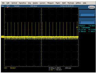
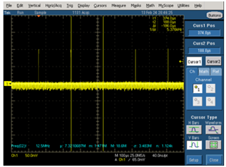
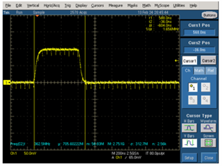
In PCIe applications, transmitter - while it is in high impedance - sends out pulses until it realizes a change in RC time constant of the response. For further details note This FAQ. For further details, note scope shots of RX detect pulses below:
1). RX detect pulses:

2). RX detect pulse frequency:

3). RX detect pulse width:

Regards, Nasser
Part Number: DS90UB971-Q1
Tool/software:
How can I optimize my FPD-Link ADAS design to achieve better performance in system level ESD immunity testing? When striking my system with ESD pulses, I observe visual glitches, loss of video frames, or black screens.