TI E2E support forums
  • User
  • Site
  • Search
  • User
  • E2E™ design support >
  • Forums
    • Amplifiers
    • API solutions
    • Audio
    • Clock & timing
    • Data converters
    • DLP® products
    • Interface
    • Isolation
    • Logic
    • Microcontrollers
    • Motor drivers
    • Power management
    • Processors
    • RF & microwave
    • Sensors
    • Site support
    • Switches & multiplexers
    • Tools
    • Wireless connectivity
    • Archived forums
    • Archived groups
  • Technical articles
  • TI training
    • Tech days
    • Online training
    • Live events
    • Power Supply Design Seminar
  • Getting started
  • 简体中文
  • More
  • Cancel
Interface

Interface

Interface forum

  • Mentions
  • Tags
  • More
  • Cancel
  • Ask a new question
  • Ask a new question
  • Cancel
Texas Instruments (TI) Interface support forum is an extensive online knowledge base where millions of technical questions and solutions are available 24/7. You can search interface IC content or ask technical support questions on everything from ESD protection to interfacing with USB, Ethernet, and HDMI. Find the right solution for your circuit design challenges by using our TI E2E™ support forums that are supported by thousands of contributing TI experts.
Frequent questions
    • 4/30/2025
    • Ethan Sempsrott

    [FAQ] LVDS / M-LVDS Transceiver Resources

    [Click here to return to Transceiver Homepage]

    Welcome to the LVDS / M-LVDS Transceivers E2E page!

    Listed below are a variety of resources to assist with the implementation of Low Voltage Differential Signaling, also know as LVDS!


    LVDS / M-LVDS Basics:

    • How far and how fast can you operate LVDS drivers and receivers?
    • How to terminate LVDS connections
    • What performance can LVDS achieve with different cabling?
    • How to interface between an LVDS driver and a sub-LVDS receiver
    • How to Use a 3.3-V LVDS Buffer as a Low-Voltage LVDS Driver
    • How to Support 1.8-V Signals Using a 3.3-V LVDS and a Level-Shifter
    • What is failsafe biasing? How do I setup failsafe biasing for LVDS?
    • How do I estimate LVDS power consumption?
    • How can I reduce jitter in LVDS?

    M-LVDS:

    • What is M-LVDS? What are the design guidelines?
    • How far and how fast can you operate M-LVDS transceivers?
      • Similar but older article: M-LVDS Signaling Rate Versus Distance

    Additional resources:

    • How to use LVDS to improve EMC in Motor Drives
    • How do I support low voltage I/O signals into an FPGA, Professor, or ASIC with LVDS?
    • How to use LVDS as a high-speed comparator
    • How to convert HDMI/DVI to LVDS/OLDI
    • Applications of LVDS in Ultrasound Scanners
    • Applications of LVDS with LEDs
    • How old of a date code is too old? Do ICs expire?
    Interface forum Interface
    • 4/28/2025
    • Ethan Sempsrott

    [FAQ] RS-485 / RS-422 Transceiver Resources

    [Click here to return to Transceiver Homepage]

    Welcome to the RS-485 / RS-422 Transceivers E2E page!

    Listed below are a variety of resources to assist with the implementation of RS-485 and RS-422!

    Note that many RS-485 resources also apply to RS-422


    RS-485 / RS-422 Basics:

    • RS-485 Video Series
    • RS-422 and RS-485 Standards Overview and System Configurations
    • The RS-485 Design Guide
    • Mitigating UART receiver glitches while switching modes

    Frequently Asked Questions (FAQ):

    • Why are termination resistors necessary? How do I terminate an RS-485 system?
    • Is 54 Ohm termination recommended? What is the difference between 120 Ohm and 54 Ohm?
    • What is external fail-safe? Why is fail-safe helpful?
    • How old of a date code is too old? Do ICs expire?
    • Are 3.3V and 5V RS-485 transceivers compatible? 
    • Can galvanic isolation be used in RS-485 with a transformer?
    • What is the difference between RS-422 and RS-485?
    • How to calculate power consumption for RS-485?
    • What are some recommended RS-485 transceivers?

    IEC ESD, EFT, and Surge Information:

    • How do I protect RS-485 from IEC ESD, EFT, and Surge?
    • What devices does TI have with integrated surge protection?
    • High EMC Immunity RS-485 Reference Design
    • What are some recommend devices for IEC ESD protection in RS-485?
    • What is an EFT? Part 1
    • What is an EFT? Part 2
    • What are the IEC 61000 4-2, 4-4, and 4-5 standards?
    • What are the differences between Human Body Model (HBM) and IEC 61000 4-2? 

    Special Functions of Select RS-485 devices:

    • What is Auto-direction? Why is it useful?
    • Flexible RS-485: Simplified Multi-System Design
    • Multiprotocol Transceivers with THVD44xx
    • Receiver Equalization for extending RS-485 distance and data rate

    Power Line Communication Using Powerbus (OOK modulated RS-485):

    • THVD80x0 Design Guide
    • Low Voltage AC Design Guide with THVD80x0
    • High Voltage or Low Bus Impedance Design Guide with THVD80x0
      • High Voltage or Low Impedance Reference Design with THVD80x0
    • Classical RS-485 vs Powerbus
    • Star Networks with THVD80x0
    Interface forum Interface
    • 4/9/2025
    • Nick Peabody

    [FAQ] LMH1297: Manually Adjusting Cable EQ

    Part Number: LMH1297

    Tool/software:

    Hi,

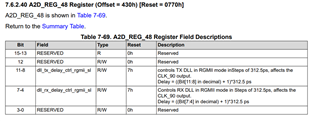
    When performing diagnostic evaluations of the LMH1297 retimer customers often want to adjust input cable EQ from the IO side. In these cases we recommend disabling the EQ adaptation and performing the following register sequence to manually adjust the cable EQ:

    Command Register Value Mask
    //Select the ConfigIO page 0xFF 0x05 0x05
    //Disable EQ Adaptation 0x00 0xC0 0xC0
    //Write the cable EQ value 0x24 xx 0x1F
    //Read the cable EQ value 0x25 xx 0x1F

    After writing the cable EQ value in ConfigIO register 0x24, read the updated value in 0x25 to ensure that the device's cable EQ value has changed.

    Best regards,

    Nick 

    Interface forum Interface
    • 4/8/2025
    • Ethan Sempsrott

    [FAQ] CAN Transceiver Resources

    [Click here to return to Transceiver Homepage]

    Welcome to the CAN Transceivers E2E page!

    Listed below are a variety of resources to assist with the implementation of the Controller Area Network, aka CAN!


    Frequently Asked Questions (FAQs):

    • Can 3.3V and 5V CAN transceivers operate on the same bus together?

    • My MCU uses 3.3V as the logic supply, do I need a 3.3V CAN transceiver?

    • What is CAN SIC (Signal Improvement Capability)? How does this improve my network?

    • What resources are available for programming with CAN controllers?

    • What is the function of the SPLIT pin on a CAN transceiver?

    • How can the power consumption of a CAN transceiver in active operation be calculated?

    • What are the different types of CAN implementations available in C2000 devices?

    • What are the CAN ESD protection recommendations?

    • What is the common mode voltage for CAN?

    • What is the difference between standard and split termination?

    • How do I find TI quality, reliability, and material reports?

    • When do I need to Isolate CAN? How do I use CAN isolated devices?

    • What power rating is needed for the CAN termination resistor?

    • Is it possible to use CAT5 Ethernet cables for CAN? 

    TI Guides, Reports, and more:

    • CAN Video Series

    • Overview of 3.3V CAN Transceivers

    • Common Mode Chokes in CAN Networks: Source of Unexpected Transients

    • Introduction to the Controller Area Network (CAN)

    • Protecting Automotive Can Bus Systems from ESD Overvoltage Events

    • CAN transceiver EMC and other compliance reports

      • Note: this is an internal resource only. For assistance with documentation, reach out to TI customer service, TI FAE, or TI sales representative.

    • Semiconductor and IC Package Thermal Metrics

    Interface forum Interface
    • 4/8/2025
    • Ethan Sempsrott

    [FAQ] Interface Transceivers: E2E Homepage

    Welcome to the Interface Transceivers E2E page!

    Here you will find a variety of resources that support our long list of devices (750+ and counting!)


    Select an interface below to find a collection of FAQs, application notes, videos, and more:

    RS-485 / RS-422

    RS-232

    IO-Link

    LVDS

    CAN

    LIN

    System Basis Chips (SBC)

    Interface forum Interface
    • 4/7/2025
    • Evan Su

    [FAQ] DS320PR810: How should PCIe signals be AC coupled?

    Part Number: DS320PR810

    Tool/software:

    How do I check to make sure my PCIe signals are AC-coupled correctly?

    Interface forum Interface
    • 4/1/2025
    • Nick Peabody

    [FAQ] DP83TC812S-Q1: RGMII Shift and Align Mode

    Part Number: DP83TC812S-Q1

    Tool/software:

    Hello,

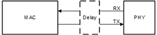
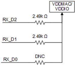
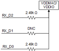
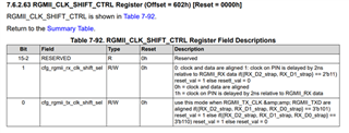
    Here is a summary of available information about RGMII Shift and Align mode for our DP83TC81x devices:

    • A minimum of 1ns setup and 1ns hold time must be maintained at the input of the receiver. 
    • The delay can be added by PCB traces, by the PHY or by the MAC
    • Either way, it is based on the RGMII input timing specifications and must be maintained.
    • RGMII shift mode means there is an added delay. RGMII align mode means there is no added delay.
    • TX Delay
    • TX + RX delay
    • CLK Shift registers
    • The maximum programmable delay by our PHYs is 5 ns and the default is 2.5 ns.
    Interface forum Interface
    • 4/1/2025
    • Nick Peabody

    [FAQ] LMH1239: SDI Layout Suggestions

    Part Number: LMH1239

    Tool/software:

    Hello SDI engineers and LMH enthusiasts,

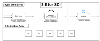
    Figure 1 - 3:5 for SDI

    In this E2E FAQ, I will be discussing GND plane layout best practices for SDI designs. In cable driver designs, see figure 1, SDI data transitions between 50 ohms differential and 75 ohm single ended characteristic impedances as the means of transport. 

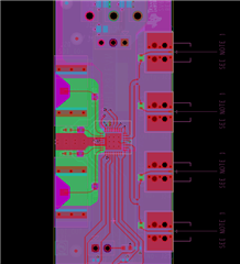
    Figure 2 - LMH1297 layout

    Figure 2 illustrates the way TI adjusts the PCB layout to content with this change in characteristic impedance change. The green section shows the GND reference at Layer 3 of the board for the 75 ohm single ended signals. The increase in distance between the traces and the reference plane increases the characteristic impedance on the trace. 

    All current must flow in a closed loop and return to its source. The goal of using a reference plane is to reduce emissions like crosstalk. The current will return to its source somehow, and it is in the designers best interest to ensure that the flow is predictable.

    Best regards,

    Nick

    Interface forum Interface
    • 3/10/2025
    • Shane Hauser

    [FAQ] TDP142: Linearity Range Description

    Part Number: TDP142

    Tool/software:

    Hi Experts,

    What does 'Linear range' refer to on re-drivers like TDP142, TDP1204, TDP2004,...?

    Interface forum Interface
    • 2/27/2025
    • McKenzie Eaker

    [FAQ] Device Mismarked with A5

    The device I received is marked as 'A5' but that is not listed as an option in the datasheet. 

    Interface forum Interface
<>

View FAQ threads
  • Tags
  • RSS
  • More
  • Cancel
  • Not Answered

    HD3SS215EVM: Differential Impedance for HDMI2.0 Compliance Test 0 Locked

    860 views
    2 replies
    Latest over 8 years ago
    by Sadanori Kato
  • Answered

    TLK10031: question about power dissipation 0 Locked

    626 views
    1 reply
    Latest over 8 years ago
    by Luis Omar Moran
  • Answered

    SN65HVD231: VREF pin connection 0 Locked

    578 views
    1 reply
    Latest over 8 years ago
    by Hao L
  • Not Answered

    TMDS442: reference schematic 0 Locked

    510 views
    1 reply
    Latest over 8 years ago
    by Moises Garcia
  • Answered

    SN65HVD72: SN65HVD72 output differential voltage 0 Locked

    959 views
    4 replies
    Latest over 8 years ago
    by Miguel Robertson
  • Answered

    TPL7407L: the treatment for unsed pin IN7 0 Locked

    580 views
    1 reply
    Latest over 8 years ago
    by Aleksandras_Kaknevicius
  • Answered

    ONET4211LD: Standalone working 0 Locked

    1636 views
    4 replies
    Latest over 8 years ago
    by Sriharsha Kota Pavan
  • Suggested Answer

    XIO2213B: How to improve the 1394b iso-packet performance 0 Locked

    1657 views
    11 replies
    Latest over 8 years ago
    by Clemens Ladisch
  • Answered

    TPS65982: new project with Alpine Ridge 0 Locked

    777 views
    2 replies
    Latest over 8 years ago
    by K.Yaita
  • Not Answered

    PCA9306: Need to know the Input and output Voltage levels 0 Locked

    1690 views
    2 replies
    Latest over 8 years ago
    by Kiran A
  • Answered

    TPS2549-Q1: Not use TPS2549-Q1 current limit detect 0 Locked

    768 views
    4 replies
    Latest over 8 years ago
    by Akihisa Tamazaki
  • Not Answered

    TPS65983: TPS65983 Application Question for Intel's Alpine Ridge' 0 Locked

    826 views
    2 replies
    Latest over 8 years ago
    by Wen Yung
  • Answered

    SN65LVDS179: unused pin 0 Locked

    798 views
    1 reply
    Latest over 8 years ago
    by Gerardo
  • Answered

    TPS65986: TPS65986 about USB3.0 0 Locked

    500 views
    1 reply
    Latest over 8 years ago
    by Eric Beljaars
  • Suggested Answer

    TPD2E2U06: Protection details 0 Locked

    1009 views
    3 replies
    Latest over 8 years ago
    by Brian Dempsey
  • Answered

    TPS65982: TPS65982 FW update with USB EP 0 Locked

    674 views
    1 reply
    Latest over 8 years ago
    by Eric Beljaars
  • Not Answered

    TLK1501: High speed intervonnction of two FPGA's 0 Locked

    852 views
    1 reply
    Latest over 8 years ago
    by Luis Omar Moran
  • Not Answered

    SN75DP159: Vdd power supply max ripple 0 Locked

    667 views
    1 reply
    Latest over 8 years ago
    by Moises Garcia
  • Answered

    HD3SS3220: HD3SS3220 use of VDD5 0 Locked

    847 views
    5 replies
    Latest over 8 years ago
    by Diego Cortes
  • Not Answered

    Linux/SN65LVDS324: SN65LVDS324 HiSPI CRC Error Issue 0 Locked

    434 views
    1 reply
    Latest over 8 years ago
    by Gerardo
<>