TI E2E support forums
  • User
  • Site
  • Search
  • User
  • E2E™ design support >
  • Forums
    • Amplifiers
    • API solutions
    • Audio
    • Clock & timing
    • Data converters
    • DLP® products
    • Interface
    • Isolation
    • Logic
    • Microcontrollers
    • Motor drivers
    • Power management
    • Processors
    • RF & microwave
    • Sensors
    • Site support
    • Switches & multiplexers
    • Tools
    • Wireless connectivity
    • Archived forums
    • Archived groups
  • Technical articles
  • TI training
    • Tech days
    • Online training
    • Live events
    • Power Supply Design Seminar
  • Getting started
  • 简体中文
  • More
  • Cancel
Interface

Interface

Interface forum

  • Mentions
  • Tags
  • More
  • Cancel
  • Ask a new question
  • Ask a new question
  • Cancel
Texas Instruments (TI) Interface support forum is an extensive online knowledge base where millions of technical questions and solutions are available 24/7. You can search interface IC content or ask technical support questions on everything from ESD protection to interfacing with USB, Ethernet, and HDMI. Find the right solution for your circuit design challenges by using our TI E2E™ support forums that are supported by thousands of contributing TI experts.
Frequent questions
    • 10/1/2024
    • Drew Miller1

    [FAQ] DS280DF810: The new set of DS2x0DFx10 devices Version IDs do not match the Version IDs of previous set (Register 0xF0)

    Part Number: DS280DF810

    Tool/software:

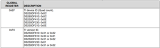
    In TI's DS2x0DFx10 Ethernet retimer devices, there is a Version ID register that can be used to read back the device version.  For groups implementing this device, we frequently see them checking this Version ID to confirm that the DS2x0DFx10 is correctly installed in their system and responding.

    Sometimes, TI receives questions about why the Version ID is not matching expectations.  The primary cause for this is that some DS2x0DFx10 devices have multiple valid Version IDs.  For example, the DS280DF810 has valid Version IDs of 0x30 or 0x31.

    The table below is an excerpt from the DS2x0DFxx0 Programmer's Guide. This shows valid Version IDs for multiple 25G/28G retimer devices.  For the latest set of Version IDs, please reference the DS2x0DFxx0 Programmer's Guide.

    Interface forum Interface
    • 10/1/2024
    • Drew Miller1

    [FAQ] DS110DF111: Does TI's Ethernet Signal Conditioning Portfolio Support Base-T Ethernet?

    Part Number: DS110DF111

    Tool/software:

    Texas Instruments has a wide range of signal conditioning devices for Ethernet.

    Sometimes we receive questions regarding a signal conditioning device's ability to support Base-T Ethernet.  The majority of TI's Ethernet signal conditioning portfolio only supports NRZ signaling.  The exception to this (at the time of writing) are the DS560xxxxx devices, which support NRZ and PAM4 signaling.

    Base-T Ethernet uses different signaling levels than those supported by TI's Ethernet signal conditioning devices.  The devices below are unable to support signal conditioning for Base-T Ethernet protocols such as 1GBase-T, 2.5GBase-T, and 10GBase-T.

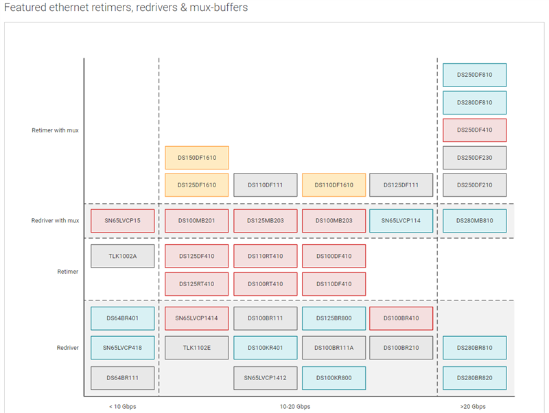
    Please see TI's Ethernet Signal Conditioning portfolio to review support for other Ethernet protocols.

    https://www.ti.com/interface/ethernet/retimers-redrivers-mux-buffers/overview.html

    Interface forum Interface
    • 9/30/2024
    • Vishesh Pithadiya

    [FAQ] Measuring the maximum drive distance of a signal conditioner across a cable

    Part Number: TDP1204

    Tool/software:

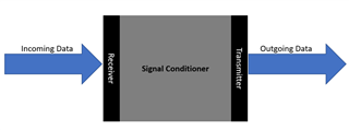
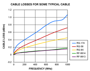
    Most redrivers and retimers advertise their equalization capabilities in dB but its difficult to quantify what that represents in terms of cable length. This FAQ is a guide to determine how long of a cable can be supported by a signal conditioner.

    1. Determine if the cable will be connected on the receiver end or transmitter end of the signal conditioner
      1.                                                                                                                                                                                                                                                                                                                                       
    2. When using a signal conditioner where the cable will be connected to the receiver end, the biggest care about is the receiver equalization (RX EQ). This value is a key attribute of any signal conditioner and will be available on the signal conditioner datasheet, keep in mind this RX EQ value will be at a defined frequency or datarate. The relationship is 2x frequency = datarate Locate and note this RX EQ value and the frequency.
      1. The cable you are planning to use for cable reach testing must be a cable that has passed compliance and is within tolerances of the defined protocol specification
        1. For example, an HDMI cable is defined in the HDMI specification under section 5, and the electrical specification can be found under section 5.1.1.1
        2. A cable vendor must pass testing to prove its parameters are within the defined specification.
      2. The cable vendor will have information regarding the loss of the cable at a defined frequency of signaling. Ideally, they have a bode plot defining the loss of a cable across a variety of frequencies.
        1. Here is an example of a cable loss plot:
        2. Increasing the frequency of signaling will always result in more loss. Because of this relationship always test max cable reach at the maximum data rate intended for use. Continuing with the HDMI example, the maximum datarate for HDMI2.1 is 12Gbps. This means the signal frequency of interest is 6GHz.
      3.  After gathering the loss profile of the cable and the RX EQ capability of the signal conditioner, you are ready to determine the maximum cable length with that vendor. This becomes a simple division problem
        1. [RX EQ (dB)/ Loss profile (dB/m) = total length (m)]                                                                                                                                                                                                                                                                                                                                                                                                         
    3. When looking at a signal conditioner where the cable will be connected on the TX end, the process becomes a little more abstract. This is because we will not know the receiver equalization capability.
      1. The first step is to verify that the cable used follows the electrical characteristics defined in the protocol specification.
      2. The next step is to run protocol compliance with the maximum TX driver settings
        1. This includes but is not limited to, slew rate, voltage swing, pre-emphasis, and de-emphasis.
        2. When running compliance make sure that there is no cable model being applied on top of the existing physical cable used for compliance. For example, in HDMI compliance testing there is a short-cable model eye diagram and a long-cable model eye diagram.
          1. In the short-cable model there is a small loss profile added onto the exiting physical cable so results will be marginally worse than expected.
          2. However, the long cable model adds the loss profile of the worst possible cable that is defined in the HDMI spec. This loss profile will be added on top of the physical cable being tested. This most likely will fail the eye diagram test, but is not cause for concern as this test is a moot point.
        3. Determine the maximum physical cable length that can be used by using the longest cable tested with a passing compliance report. This can also be verified functionally by plugging in the TX to a data sink.
    Interface forum Interface
    • 9/30/2024
    • Brian Zhou

    [FAQ] Why TUSB804x hub can not be detected in SMBUS mode

    Part Number: TUSB8042A

    Tool/software:

    When the SMBus interface mode is enabled, the TUSB804x supports read block and write block protocols as a receiver-only SMBus device.

    The TUSB804x will wait indefinitely for configuration by the SMBus host and will not connect on the upstream port until the SMBus host indicates configuration is complete by clearing the CFG_ACTIVE bit.

    CFG_ACTIVE bit is on register 0xF8h.

    Best 

    Brian

    Interface forum Interface
    • 9/30/2024
    • Brian Zhou

    [FAQ] TUSB8041A: what is difference between I2C mode and SMBUS mode for TUSB80xx hub

    Part Number: TUSB8041A

    Tool/software:

    In I2C mode, Hub is master and I2C is used to read / write external EEPROM . Hub configuration  can be changed by reading external EEPROM

    In SMBUS mode, hub is receiver, you can change  hub configuration  by  changing  hub register with SMBUS.

    Best

    Brian

    Interface forum Interface
    • 9/30/2024
    • Evan Su

    [FAQ] DS320PR810: How should redriver thermal vias and solder paste patterns be designed?

    Part Number: DS320PR810

    Tool/software:

    Why do we need to consider thermal vias and solder paste for redrivers at the board layout stage, and how should they be handled?

    Interface forum Interface
    • 9/30/2024
    • Nick Peabody

    [FAQ] LMH1229: Understanding Jitter Measurements

    Part Number: LMH1229

    Tool/software:

    To understand the overall jitter measurement it is important to understand what jitter is. All system jitter measurements have components of Deterministic Jitter (DJ) and Random Jitter (RJ) that sum to make the Total Jitter (TJ). DJ is the amount of jitter that is certain to the system, it is predictable and repeatable, so no matter how long the system is running the DJ will stay the same. RJ is random and increases exponentially with time. RJ causes all eyes to close if the system is left on forever, but that is not useful to engineers because we do not live forever. So, it is essential that we make a common threshold for the transmitted bits. A common threshold for measurement is 1E12 bits. 

    Now into the jitter measurements we can take. The first is the Time Interval Error (TIE). The TIE is the amount of time that the actual bit transition strays from the expected position for transition. The TIE can be displayed in a gaussian (normal) distribution histogram.

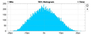
    As the distribution moves further and further from the mean and towards the 3 sigma and -3 sigma regions of the distribution, the number of hits strongly decreases. A useful component of the TIE histogram is that the width of the histogram in ps shows the density of the transition point of the eye diagram. 

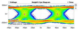
    Notice how the width of the transition point for the eye diagram is the same as the width of the histogram ~40 ps.

    Another measurement is the BER bathtub. The bathtub is a visualization tool for the TJ's effect on the eye closure. As the number of bits increases from one, the eye closure increases as RJ increases.

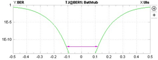
    Notice that at 1E12 bits the eye is closed by ~0.8 UI which is 67 ps of closure for 12G SDI. 

    With these three components of measurement it is possible to visualize the effects of jitter on eye closure. The jitter directly corresponds to the horizontal shrinkage of the eye diagram.

    Best Regards,

    Nick

    Interface forum Interface
    • 9/27/2024
    • Ryan Kitto

    [FAQ] TUSB211A: My USB2 Redriver is not boosting when enabled during testing.

    Part Number: TUSB211A

    Tool/software:

    I am enabling my TUSB211A while running test packets through our setup, but I am not seeing any boost. Why is that?

    Interface forum Interface
    • 9/27/2024
    • Ryan Kitto

    [FAQ] TMUXHS221: Alternate Signaling Mux Selection

    Part Number: TMUXHS221

    Tool/software:

    I want to mux signals with a range of bandwidths equal to or lower than USB3.0 data rates without getting a full USB3 mux. What would be the best mux for this?

    Interface forum Interface
    • 9/25/2024
    • Shane Hauser

    [FAQ] TUSB1002A: How to pass USB receiver JTOL compliance with a linear re-driver

    Part Number: TUSB1002A

    Tool/software:

    Hi Experts,

    How do I pass USB3 RX JTOL compliance with the TUSB1002A?

    Interface forum Interface
<>

View FAQ threads
  • Tags
  • RSS
  • More
  • Cancel
  • Not Answered

    LVDS Driver/Receiver Question 0 Locked

    171 views
    1 reply
    Latest over 12 years ago
    by Nasser Mohammadi
  • Not Answered

    Tablet screen connected to a laptop board 0 Locked

    442 views
    1 reply
    Latest over 12 years ago
    by Elias Villegas M.
  • Not Answered

    DS100MB203SQ via information 0 Locked

    160 views
    1 reply
    Latest over 12 years ago
    by Nasser Mohammadi
  • Answered

    About the power sequence of DP83865 0 Locked

    342 views
    2 replies
    Latest over 12 years ago
    by Patrick OFarrell
  • Answered

    About RSVD pin of TFP403 0 Locked

    947 views
    3 replies
    Latest over 12 years ago
    by Elias Villegas M.
  • Not Answered

    TUSB73320 running at Gen1 speeds 0 Locked

    261 views
    3 replies
    Latest over 12 years ago
    by Diego Cortes
  • Answered

    TLK106 storage temperature range 0 Locked

    398 views
    1 reply
    Latest over 12 years ago
    by Patrick OFarrell
  • Not Answered

    PCI2050B / supply current 0 Locked

    393 views
    5 replies
    Latest over 12 years ago
    by Ryuji
  • Not Answered

    TUSB1310A PHYSTATUS SIgnal is not working properly 0 Locked

    345 views
    0 replies
    Started over 12 years ago
    by VIKAS GUPTA1
  • Not Answered

    PCA9548A - SDA latching to low at power up 0 Locked

    371 views
    1 reply
    Latest over 12 years ago
    by Sadanori Kato
  • Not Answered

    DS50PCI402 unused input 0 Locked

    255 views
    2 replies
    Latest over 12 years ago
    by Toshi
  • Not Answered

    TUSB7340 soldering issue 0 Locked

    296 views
    1 reply
    Latest over 12 years ago
    by Jeffery Pfarr
  • Answered

    DS90UB913Q/DS90UB914Q Recommended Register Values 0 Locked

    261 views
    3 replies
    Latest over 12 years ago
    by Ryan Bailey
  • Not Answered

    M-LVDS hot plugging with SN65MLVD040 0 Locked

    1846 views
    7 replies
    Latest over 12 years ago
    by jan.emdep.cat
  • Answered

    LMH0034 competitive analysis with Gennum device 0 Locked

    496 views
    1 reply
    Latest over 12 years ago
    by Mark Sauerwald88474
  • Answered

    TUSB7320 - Is there the USB3.0 compliance test data (report)? 0 Locked

    270 views
    1 reply
    Latest over 12 years ago
    by Alexis Cortes9585
  • Not Answered

    MCP6S28 interfacing with stellaris 0 Locked

    252 views
    1 reply
    Latest over 12 years ago
    by Andrew_Mason
  • Answered

    About the minus voltage output of "SN55LBC173" 0 Locked

    320 views
    2 replies
    Latest over 12 years ago
    by hisakichi kobayashi
  • Not Answered

    sn65lvdt32b internal terminations 0 Locked

    276 views
    1 reply
    Latest over 12 years ago
    by Jim Dietz
  • Not Answered

    MCP6S28 interfacing 0 Locked

    189 views
    0 replies
    Started over 12 years ago
    by Srinivas Prasad1
<>