Part Number: TLK10232EVM
FAQ: I received TLK10232EVM kit that does not have USB cable, power cables, CD-ROM, or EVM User's Guide, as mentioned in TLK10232EVM User's Guide. Did I receive an incomplete EVM kit?
Part Number: TXE8124-Q1
Tool/software:
FAQ: Logic and Voltage Translation > IxC and SPI >> VOH/IOH/VOL/IOL and Total ICC Current Definitions
This FAQ describes 6 key spec's for I/O expanders.
These specs include:
These electrical specs apply to both I2C and SPI I/O expanders from Texas Instruments. For this example, we will look at TXE8124-Q1
VOH / VOL / IOH / IOL:
The general output structure of the TXE81xx looks as the following:
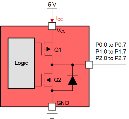
Q1 and Q2 make up the push-pull output structure of the I/O expander. There is an ESD protection diode on the I/O that points from GND to the I/O pin. Q2 is an n-type MOSFET while Q1 is a p-type MOSFET. Both transistors are used to create the high and low logic outputs out to the I/O pins P0.0 - P2.7.
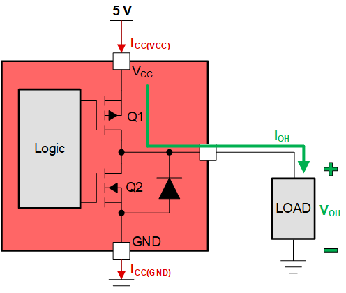
For example, when driving an output HIGH, Q1 is enabled while Q2 is disabled. Q1 pushes current out of the pin by driving the pin towards VCC. VOH is the output HIGH voltage while IOH is the output HIGH current being sourced.
Conversely, when driving an output LOW, Q2 is enabled while Q1 is disabled. Q2 pulls current out of the LOAD by driving the I/O pin towards GND. VOL is the output LOW voltage while IOL is the output LOW current being sank.
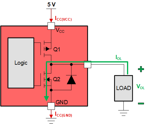
This is the "push/pull" circuit where current is being pushed out or pulled into the TXE81xx I/O expander. The type of load being driven will determine the output voltage and output current seen at the I/O pin. See the electrical characteristics from the datasheet.

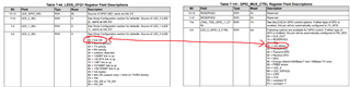
P port is highlighted for I/O pins P0.0 - P2.7.
This table shows the maximum and minimum voltages seen for VOH or VOL. The push-pull driver is characterized by these numbers. For example, when VCC = 5.5 V, you can expect your output voltage VOH to be at least 4.95 V when sourcing 8 mA of current (IOH) out of the pin. In theory, the pFET driver has an equivalent drive strength resistance of at least R = (5.5 V - 4.95 V) / 8 mA = 68.75 ohms. When an output logic HIGH is asserted on the I/O pin, it is effectively connecting a pull-up resistance of 68.75 ohms through the pFET driver.
When reading the table for VOL, you can expect a VOL(max) = 0.22 V when VCC = 1.65 V, and the TXE is sinking 4 mA of current (IOL).
The SPI data output SDO also has driver characteristics because it is also a push-pull driver. SDO drives data back to the MCU with these driver characteristics of VOH and VOL.
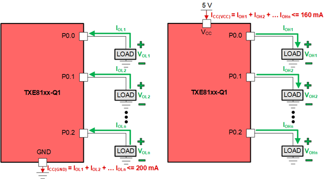
ICC(GND) and ICC(VCC) - Abs. Max Specifications:
The absolute maximum specifications are found in section 5.1 - Absolute Maximum Ratings in the datasheet.
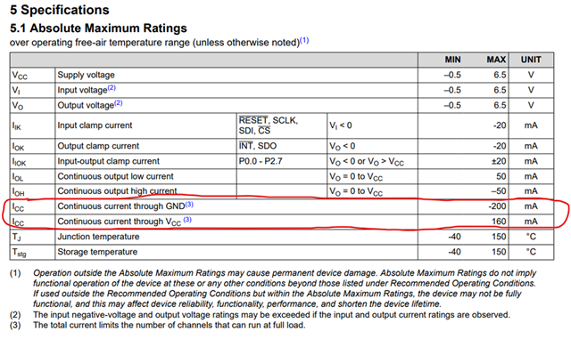
The high-lighted specs are ICC - continuous current through GND, and ICC - continuous current through VCC. These spec's are critical to consider because I/O expanders can have many pins configured to OUTPUT where several loads are being driven at a single time.
The examples above was showing a single I/O pin driving an output and sinking/sourcing a current through a load. When using TXE8116, TXE8124, or TXE8148, there can be 16 / 24 / 48 outputs simultaneously driving a load. If these total currents exceed the absolute maximum ratings for VCC or GND, potential damage may occur to the device.
Below is an example of the additive current sink and source for driving several outputs. Consider that the I/O expander has a total current budget of which all the I/O's configured as output contribute to.
[Click here to return to Transceiver Homepage]
Welcome to the IO-Link Transceivers E2E page!
Listed below are a variety of resources to assist with the implementation of IO-Link!
IO-Link Basics:
Design Resources:
Part Number: TXE8116-Q1
Tool/software:
FAQ: Logic and Voltage Translation > IxC and SPI >> What is the Difference Between I2C and SPI IO Expansion?
Both I2C and SPI I/O expansion solve the fundamental problem of I/O shortages. An MCU may run out of usable I/O's and therefore needs I/O expansion by using either the I2C bus or SPI protocol. The main differences between the two come down to the peripheral's features. We can analyze two devices in the market today that describe the main differences between using I2C vs. SPI I/O expansion when it comes to TCAL6416 and TXE81xx (TXE8116 / TXE8124 / TXE8148).
| Spec | I2C - TCAL6416 | SPI - TXE8116/24/48 |
| Voltage Range | 1.08 V to 3.6 V | 1.65 V to 5.5 V |
| Data Rate | 1 MHz | up to 10 MHz |
| # of wires required for communication? | 2 | 4 |
| IO Count | 16 | 16 / 24 / 48 |
| Dual Supply? | Yes | No |
| /RESET? | Yes | Yes |
| /INT? | Yes | Yes |
| Requires Addressing? | Yes, ADDR pin gives 2 unique addresses | No, requires separate CS line for each IO expander (one CS for daisy chaining) |
| Ambient Temperature? | -40C to 125C | -40C to 125C |
| ICC (Standby Current) | 14 uA | 26 uA |
| 5V Tolerant I/O's? | Yes | Yes |
| Fail-safe features? | No | Yes |
| Daisy Chain? | n/a | Yes |
| VOL and IOL |
VOL = 0.2V IOL = 8 mA |
VOL = 0.15 V IOL = 8 mA |
| Multi-Port Set Feature? | No | Yes |
| Device ID Register? | No | Yes |
| Push-Pull / Open-Drain Register? | Port-wise | Individual Pin |
| Bus Holding? | No | Yes |
| Smart Interrupts / Latchable Inputs? | Yes | Yes |
| Interrupt Masking | Yes | Yes |
| Input Glitch Filter | No | Yes |
| Software Reset | Yes | Yes |
| HBM / CDM |
4000V HBM 1000V CDM |
2000 HBM 1000V CDM |
| Package Types |
TSSOP (24): 7.8 mm x 6.4 mm VSSOP (24): 6.1 mm x 4.9 mm WQFN (24): 4 mm x 4 mm |
VSSOP (32): 8 mm x 5 mm VQFN (32): 5 mm x 5 mm VSSOP (24): 6 mm x 5 mm VQFN (24): 4 mm x 4 mm |
These are some of the spec differences between the current I2C I/O expanders and newly released SPI I/O expanders.
The TXE81xx devices offer more overall functionality on the I/O pins over the agile I/O capabilities of I2C. TXE devices can operate at much higher speeds, and can operate up to 48 I/O's depending on the variant chosen.
[Click here to return to Transceiver Homepage]
Welcome to the SBC Transceivers E2E page!
Listed below are a variety of resources to assist with the implementation of SBCs, aka System Basis Chips!
SBC Basics:
Advanced SBC setup with TCAN455x:
Frequently Asked Questions (FAQs):
Part Number: TDP2004
Tool/software:
What is DisplayPort Pre-emphasis and how does a linear re-driver impacts it?
Part Number: TDP2004
Tool/software:
Hi Team,
What data rates for DP and HDMI support which resolutions?
[Click here to return to Transceiver Homepage]
Welcome to the RS-232 Transceivers E2E page!
Listed below are a variety of resources to assist with the implementation of RS-232!
RS-232 Basics:
Part Number: DP83869HM
Tool/software:
Hi Team,
What is the difference between link ok and link status in the 869 data sheet?
[Click here to return to Transceiver Homepage]
Welcome to the LIN Transceivers E2E page!
Listed below are a variety of resources to assist with the implementation of Local Interconnect Network, also know as LIN!
LIN Basics:
