Other Parts Discussed in Thread: UNIFLASH, MMWAVE-SDK, IWR6843, MMWAVEICBOOST, IWRL6432
Hi team,
Our customer was requesting assistance:
System Configuration
- Windows 11,
- CCS Studio Version :- Latest 12.2.0 (tried v8.0 and v10 as well)
- Uniflash Version 8.1.1
- MMWAVE-SDK Version 3.05.x.x
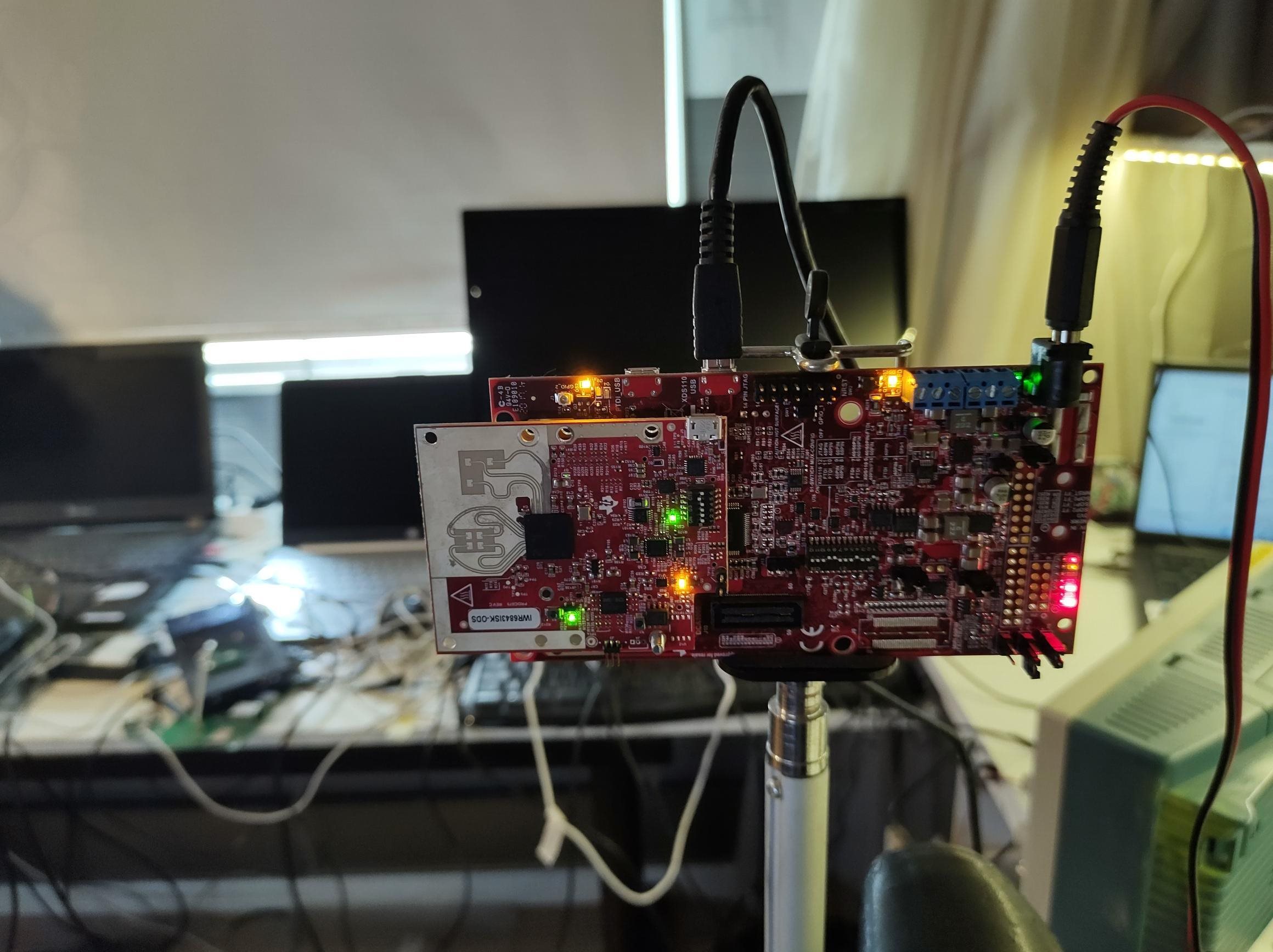
- Radar Board : IWR6843-ISK-ODS
- BoostBoard : MMWAVE BOOST
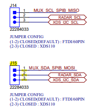
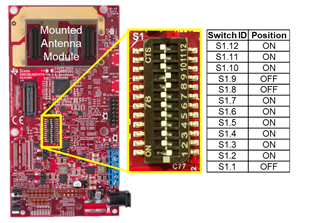
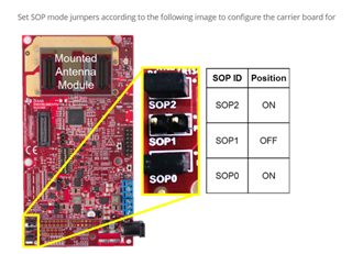
I’m able to flash the IWR6843-ISK-ODS (radar board) individually, but When I Connect IWR6843-ISK-ODS Board With MMWAVEBOOST and Configure it as a Flashing mode through jumper Settings. it failed, I'm trying to flash a binary image to the board but it shows an error. Below I have provided more details.Below image I have configured the DIP Switch which show in below image 
Below is the configuration I have Done
Board:- IWR6843-ISK-ODS
Debugger :- Texas Instrument XDS110 USB Debug Probe
-> XDS Configuration Detail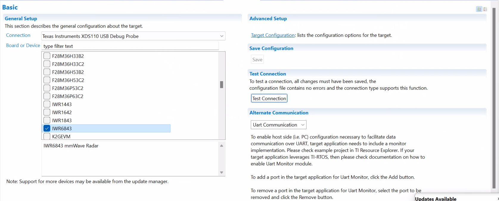
-> XDS Configuration Detail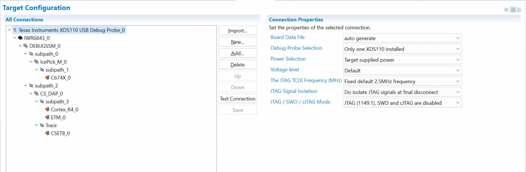
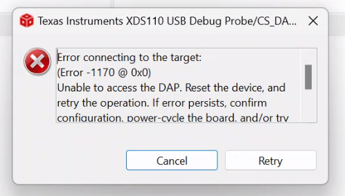
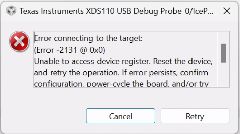
-> When Click on Test Connection, It shows an Error Below I have Provided The Logs
This utility will attempt to reset the controller.
This utility has successfully reset the controller.
-----[Print the reset-command hardware log-file]-----------------------------
The scan-path will be reset by toggling the JTAG TRST signal.
The controller is the XDS110 with USB interface.
The link from controller to target is direct (without cable).
The software is configured for XDS110 features.
The controller cannot monitor the value on the EMU[0] pin.
The controller cannot monitor the value on the EMU[1] pin.
The controller cannot control the timing on output pins.
The controller cannot control the timing on input pins.
The scan-path link-delay has been set to exactly '0' (0x0000).
-----[An error has occurred and this utility has aborted]--------------------
This error is generated by TI's USCIF driver or utilities.
The value is '-233' (0xffffff17).
The title is 'SC_ERR_PATH_BROKEN'.
The explanation is:
The JTAG IR and DR scan-paths cannot circulate bits, they may be broken.
An attempt to scan the JTAG scan-path has failed.
The target's JTAG scan-path appears to be broken
with a stuck-at-ones or stuck-at-zero fault.
[End: Texas Instruments XDS110 USB Debug Probe_0]
- I have changed target configuration With Other Option(SWD/cJTAG) but it failed.
- I Have Go through the link Provided by the TI Recommendation
Strategy for debugging JTAG connectivity problems
- I follow the All Procedure but was not able to update the new binary firmware on the IWR6843-ISK-ODS with MMWAVE BOOST.
Method 1:- Connect the MMWAVEBOOST and IWR6843 Radar Board And Try to flash with CCS Debug it shows the Same Error -2131
Method 2:- Try to Flash binary with the UNIFLASH software but it's not able to upload And through the error. below I have attached the image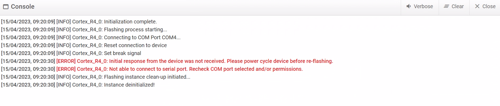
Method 3:
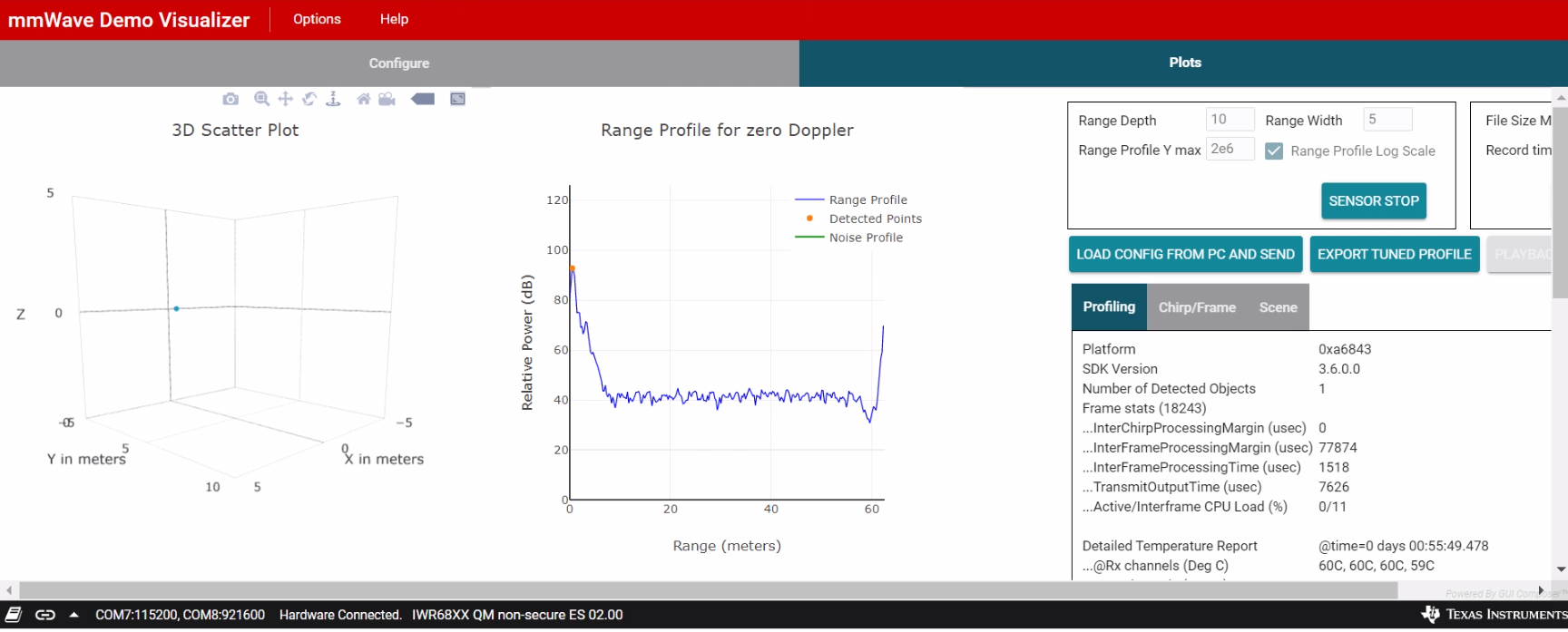
-> Flash the IWR-6843-ISK-ODS Radar board with CCS-Debug binary for specific CCS-Studio Debugging.
-> config DIP-Switch IWR-6843-ISK-ODS Radar board, and attach the MMWAVBOOST board, and try to flash with CCS Studio and UNIFLASH flasher As well.
Can you please suggest solution on this that will really help us to move forward on the project
- Is there Any Configuration missing in the above provided cases?.
- Im performing any wrong steps?
- Is Any Hardware Issue?