Part Number: IWRL6432
Steps for generating the compRangeBiasAndRxChanPhase line for the IWRL6432. Similar steps can be taken for the IWRL1432, just substitute 1432 for 6432 as appropriate.
1. Load the motion and presence demo found at C:\ti\MMWAVE_L_SDK_05_03_00_02\examples\mmw_demo\motion_and_presence_detection\prebuilt_binaries\xwrL64xx (or xwrl14xx for the IWRL1432 device).
2. Set a strong target like corner reflector at the distance of X meter (X less than 50 cm is not recommended) at boresight in a clutter-free environment. A large room or outdoors should be sufficient.
3. Add the following line to the configuration file intended for use. It is important to calibrate with a configuration file whose frequency range is similar to the range used in operation.
measureRangeBiasAndRxChanPhase 1 X D
The first argument "1" is to enable the measurement. The second argument, D, (in meters) is the distance of window around X where the peak will be searched. The purpose of the search window is to allow the test environment from not being overly constrained say because it may not be possible to clear it of all reflectors that may be stronger than the one used for calibration. The window size is recommended to be at least the distance equivalent of a few range bins.
4. Ensure that the configuration file fulfills the following constraints:
| Constraint 1 | Major Motion must be enabled |
Third argument of sigProcChainCfg must be 1 or 3 sigProcChainCfg 32 2 3 0 0 0 0 15 |
| Constraint 2 | Static Clutter Removal must be turned off | clutterRemoval 0 |
| Constraint 3 | Phase Modulation Mode must be TDM, not BPM |
Fifth Argument of chirpComnCfg must be 1 chirpComnCfg 23 0 0 256 1 65.6 0 |
| Constraint 4 |
Number of TX antennas must be 2 Number of RX antennas must be 3 |
channelCfg 7 3 0 |
An example of the changes needed can be found here in MotionDetectConfiguration.cfg
0066.MotionDetectCalibration.cfg
Use this version of the Industrial Visualizer to get output. Replace the python files in the Industrial Visualizer with those given below or just run the executable standalone.
Python Files :https://e2e.ti.com/cfs-file/__key/communityserver-discussions-components-files/1023/3630.gui_5F00_main.pyhttps://e2e.ti.com/cfs-file/__key/communityserver-discussions-components-files/1023/parseFrame.pyhttps://e2e.ti.com/cfs-file/__key/communityserver-discussions-components-files/1023/parseTLVs.py
Executable : https://e2e.ti.com/cfs-file/__key/communityserver-discussions-components-files/1023/mmWave_5F00_Industrial_5F00_Visualizer_5F00_with_5F00_Calibration.exe
Part Number: TMP61
Is there a fit replacement for the discontinued KTY81 or KTY82 PTCs?
Part Number: AWR2944
Part Number: AWR2944
If you are already working on AWR1642/AWR1843/AWR6843 (1st gen) mmWave sensor device and wondering if to move to the AWR2944 (2nd Gen) mmWave Sensor then read further.
Here is high level feature difference b/w 1st Gen and 2nd Gen mmwave Sensor (from Datasheet)
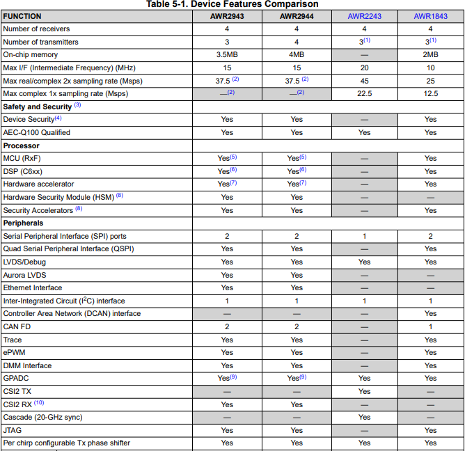
| Features | AWR2944 | AWR2243 | AWR1843 | AWR1642 |
| Max Range(m)* | 180-200 |
200-250 (single chip) 350+ (4xAWR2243 cascade) |
120-150 | 60-80 |
|
Beam forming/Steering (using Tx Phase Shifter) |
Yes |
Yes |
Yes | No |
| Usecase |
Corner Radar, Front Radar, ACC, AEB, FCW |
Front Radar, Corner Radar ACC(Adaptive Cruise Control) AEB (automated emergency Braking) AES (Autonomous Emergency Steering) FCW(Forward Collision Warning) |
ALC (Automtic Lane Change), BSD (blind spot detection) ACC, AEB, CTA (cross Traffic Alert), Parking, |
BSD, Parking, ALC, CTA |
NOTE: selection of mmWave Sensor is purely depends on your usecase and it's range/velocity/accuracy specification. Above range data based on TI EVM, device chirp/profile configuration and can be further improved using high gain antenna and processing chain. Refer this appNote to understand about object vs range https://www.ti.com/lit/an/swra593a/swra593a.pdf
Here usecase is small subset of all possible usecase with those devices, but user can extend that possibility with their application implementation.
Part Number: LDC3114
Questions: Where can I download the LDC3114 Pspice model, and what type of simulations does it support?
How should the model be configured, and how does it work with the time-varying sensor model?
The Pspice for TI model and test bench for the LDC3114 is now available for download from the Design Tools & Simulation section of the LDC3114 product folder.
The model is intended for time-domain transient simulations of the LDC3114 in raw data model.
Note that the model's netlist is encrypted for use in Pspice. It will work in the free version of Pspice for TI, and in the commercial version of Cadence Pspice.
The model will not be usable in other simulators.
No button-mode features are supported by the model.
Why?
The model’s sinusoidal sensor waveform (5MHz-30MHz) forces the Spice simulator into small time steps (~1nsec - ~10nsec) to minimize errors.
Button mode uses internal algorithms – like baseline tracking – that are meant to track environmental fluctuations (like temp) that work on much longer time scales than the sensor’s oscillator signal (e.g. minutes, hours).
Using Spice to simulate a circuit with such divergent time scales – nanoseconds versus hours – is not realistic.
The Pspice test bench also includes a time-dependent model of an inductive sensor, which can be easily modified to suit the needs of the design.
The LDC3114 model two device parameters, LCDIV and SENCYC, which control the width of the device sampling window. For more information on how these parameters affect the device behavior, please see the LDC3114 data sheet.
You should see the schematic below upon opening the test bench for the first time:
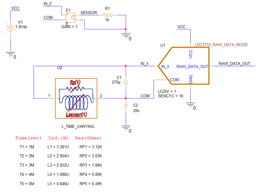
Time-varying sensor model - Calculating new values and entering them in the Pspice model
Consider the LDC3114 inductive sensor is intended to detect a moving, conductive target. As a conductive target moves closer to the inductive sensor, the sensor inductance (L) and equivalent parallel resistance (Rp) will decrease. As a target moves away from a sensor, L & Rp will increase.
This can be simulated by computing a series of L & Rp values using the Inductive Sensing Design Calculator Tool for different Target Distances, and entering the L & Rp values in the Pspice time-varying sensor model, and then running a transient sim in Pspice for TI
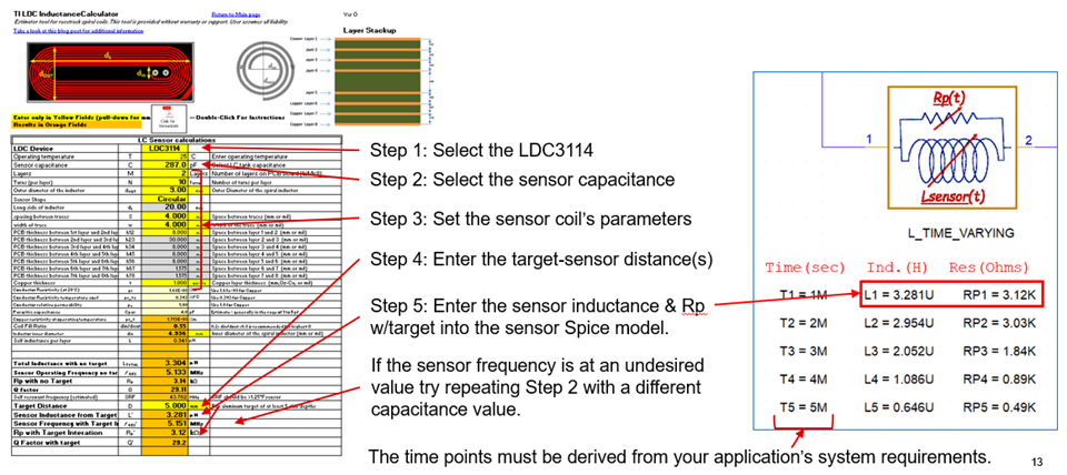
The sensor L's and Rp's can be easily calculated with the Excel-based Inductive Sensing Design Calculator Tool.
Schematic text (not shown here) describes how the default sensor L & Rp values were calculated using the calculator tool.
The following graphic outlines the steps for computing new inductor and Rp values, the then entering them in the sensor Pspice model on the schematic.
The left side of the graphic shows the landing page of the calculator tool. The middle of the graphic shows the steps for entering input parameters and noting the resulting output values for inductance and Rp for a given target distance. The right side illustrates how to enter the new inductance and Rp values in the Pspice for TI sensor model.
You can change any of the parameters of the time-varying inductor Pspice model by double-clicking on the value and entering the desired value in the pop-up.
How will the models of the time-varying inductor and the LDC3114 affect the choices of the sim conditions, and the results?
First, consider the LDC3114 model's time-related sampling parameters LCDIV and SENCYC.
The LDC3114 model has two parameters: LCDIV, SENCYC that control the sampling interval of the sensor waveform via the equation:
W=128∙(1+SENCYC)∙2LCDIV
Where: LCDIV = 1..7 (default 3)
SENCYC = 0..31 (default 4)
The time duration of the sampling interval:
tSAMPLE = W∕fSENSOR
where the LDC3114 will output a data word at the end of each sampling interval.
Example
Assume a sensor frequency fSENSOR = 10MHz, default LCDIV (= 3) and SENCYC (= 4).
The LDC3114 sampling interval will be W = 5120, and the sampling time will be tSAMPLE = W/fSENSOR = 5120/10MHz = 0.512msec.
So, for the entire sampling window – and subsequent LDC3114 data conversion – to finish successfully, the Spice sim time (TSTOP) must be > 0.512msec to capture the one sampling window.
Simulating multiple sampling windows will require multiples of the 0.512msec for Pspice transient simulation time: TSTOP ≥ N*0.512msec.
For our 10MHz sensor and the max values of LCDIV & SENCYC (7&31), the sampling window would be 52.43msec, which could result in a very l-o-n-g simulation time.
Summary: to ensure the most efficient, accurate sims, please pick the smallest possible values for LCDIV and SENCYC that will meet your application’s requirements.
Make Spice TSTOP > M∙tSAMPLE where M is the desired number of LDC sampling widows in the sim.
Next, consider the time-varying inductor model.
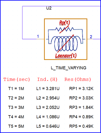
The sensor model uses two Spice TABLE structures - {TN,LN,} and {TN,RpN} – for the coil’s inductance and parallel resistance.
What are the implications?
The sensor model gives the following behavior with respect to the Pspice simulator’s transient TIME parameter:
For Spice sim TIME < T1, Lsensor = L1 and Rp = RP1.
For Spice sim TIME > T5, Lsensor = L5 and Rp = RP5.
For Spice sim TN > TIME > TN+1 Lsensor & Rp values are a linear interpolation between those values at TN and TN+1.
Example
Assume the LDC parameters from the previous slide (W = 5120, tSAMPLE = 0.512msec) will be used in a sim that includes the sensor figure shown just above.
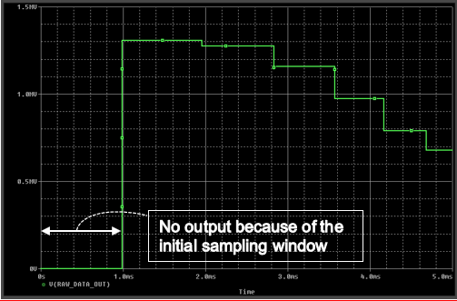
The LDC3114 model will perform conversions in nonoverlapping TIME windows with widths of 0.512msec.
The only time periods where the sensor’s inductance will be constant over the LDC3114 sampling window will be TIME < 1msec and TIME > 5msec.
As the sim TIME goes from 1msec to 5msec, the sensor L & Rp will vary over the LDC3114 sampling windows, which impact the LDC3114 raw data output after conversion of the sampling window data. Application requirements will determine if this is a realistic sim.
How will the models' parameters affect the sim results?
The plots below serve as an example of the dependence of the sim results on the models’ parameters.
The top plot uses the test bench parameter values, LCDIV = 1, SENCYC = 10.
The second plot uses the device's default values for LCDIV & SENCYC (= 3 & 4).
While the sample window (W) stays constant during each sim, the sample time (tSAMPLE) decreases during each dim because the of the time-varying sensor parameters (L & Rp) cause fSENSE to increase.
SENCYC = 10, LCDIV = 1 , W = 2816
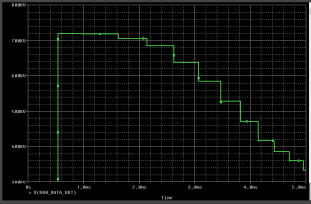
SNCYC, LCDIV = 3, W = 5120
Thank you for your interest.
If you have any questions or feedback about this model, please submit them to this E2E forum.m
Part Number: HDC3020
The HDC3 family of digital temperature and relative humidity sensors support multiple I2C addresses and the EVM for this device only supports one device at a time - is there a simple Arduino example to use which exercises more than one sensor from the same MCU?
Need help getting started with I2C communication and temperature decoding.
How would you be able to add inductive sensing to an LCD assembly to read the force of a user's touch on a car center console/information display?
Part Number: IWRL6432, AWRL6432, IWRL1432, AWRL1432
xWRL6432 and xWRL1432 are ready for evaluation!
Product folder and EVM:
Getting started guide:
Getting Started on Resource Explorer
Software Resources:
SDK 5.3
Known Issue #1 - Visualizer for KTO is not in SDK. Please find an .appimage, visualizer and configuration file for demonstrating KTO here.
SDK 5.2
Known Issue #1 - SDK 5.2 Visualizer fails with illegal multi-byte sequence. We have seen this happen when the visualizer needs to work with computers that are using Hangul/Korean characters.

Fix - Use the visualizer linked here.
https://e2e.ti.com/cfs-file/__key/communityserver-discussions-components-files/1023/visualizer.exe
SDK 5.1.0.4
Known Issues:
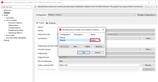
Known Issue #1 - CCS Debug Configuration does not work.
Flashing an image generated with the CCS Debug configuration (which is the default option) is not currently supported. Please switch the project to the release configuration by right-clicking the project, selecting properties->General->Manage Configurations->Select Release->Set Active->Ok->Apply and Close. When the release configuration is selected, it should look like this.
Known Issue #2 - Errors in the Out of the Box Guide for XWRL6432
We have found that there are several errors (broken paths, incorrect references) in the current Out of the Box Guide for XWRL6432. These will be corrected in a future Radar Toolbox release, but for the time being, we have the Corrected xWRL6432 Out of the Box Guide and recommend following this to reduce user confusion.
Resources to get started with CCS:
Please see this guide in the Radar Toolbox for instructions on debugging this device in CCS.
FAQs:
Common questions on this new platform will be featured here
FAQ 1 - Error message : "No valid ATE Calibration Available"
If you see this error message, it means that you inadvertently deleted all the flash on the device in the process of reprogramming it. On each device, there is a device-specific Automated Test Environment Calibration that must happen before the device can operate. You can run this calibration by flashing the ATE Calibration Image, found in $MMWAVE L SDK DIRECTORY$\tools\Ate_Calibration\xwrL64xx, onto the IWRL6432 device, putting the device in functional mode and resetting the device to allow the ATE calibration image to run, and store values on the device. Afterwards, put the device back in flashing mode, and flash the application image back onto the device. The error should resolve.
FAQ 2 - Error message :
"Error: mmWave Control Initialization failed [Error code -205848574] [errorLevel 2] [mmWaveErrorCode -3141]
Error: Boot Calibration failure
Error: mmWave Open failed [Error code: -3121 Subsystem: 0]"
This is the same error and solution procedure as FAQ 1
FAQ 3 - Demo Visualizer SDK 5.2.0.2 Chrome wasn't found
The visualizer for SDK 5.2.0.2 located at <sdk_download_location>\MMWAVE_L_SDK_05_02_00_02\tools\visualizer\Low_power_visualizer_5.2.0.2 can only be opened using google chrome.
FAQ 4 below was given a strike-thru because it is no longer relevant as of Radar Toolbox 1.20 and MMW-L-SDK 5.3
FAQ 4 - Industrial Visualizer using IWRL6432 SDK config files.
The MotionDetect.cfg and PresenceDetect.cfg configuration files will not work unmodified in the Industrial Visualizer. Each cfg file needs a newline at the end of it, and the mpdBoundaryBox line needs minZ and maxZ arguments at the end of it, which are provided in the attached CFG files.
/cfs-file/__key/communityserver-discussions-components-files/1023/MotionDetect_5F00_IND_5F00_VIZ.cfg
FAQ 5 - How do I generate the calibration coefficients for the compRangeBiasAndRxChanPhase CLI command?
See this pinned post : https://e2e.ti.com/support/sensors-group/sensors/f/sensors-forum/1254462/faq-iwrl6432-iwrl6432-comprangebiasandrxchanphase-calibration
FAQ 6 - Can my IWRL6432BOOST EVM measure the power consumed by the IWRL6432 chip?
See this pinned post : https://e2e.ti.com/support/sensors-group/sensors/f/sensors-forum/1255576/faq-iwrl6432-measuring-power-consumption-on-iwrl6432boost
FAQ 7 - How can I be sure I'm disabling memory retention banks safely?
See these two pinned posts : https://e2e.ti.com/support/sensors-group/sensors/f/sensors-forum/1273722/faq-iwrl6432-safely-decreasing-memory-retention-in-deep-sleep
FAQ 8 - Can I stream raw data off the device over UART?
Sometimes this may be possible with some limitations. See https://e2e.ti.com/support/sensors-group/sensors/f/sensors-forum/1279165/faq-iwrl6432-exporting-the-radar-cube-over-uart
