[FAQ] AM625 / AM623 / AM620-Q1 / AM62L / AM64x/ AM243x (ALV) / AM62Ax / AM62D-Q1 / AM62Px Design Recommendations / Custom board hardware design – Information on processor core, PLL, VDD_CORE, VDDR_CORE, VPP and other core supplies

Part Number: AM62L
Other Parts Discussed in Thread: UNIFLASH, , AM620-Q1, AM62P, SYSCONFIG, AM625, AM623, AM625-Q1, AM6421, SK-AM62B-P1, AM6442, AM2432, SK-AM62P-LP, AM2431, AM67A, SK-AM62A-LP, AM6548, AM62A3

Tool/software:

Hi TI Experts,

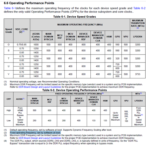
Please share your inputs on processor core, thermal alert, VDD_CORE, VDDR_CORE, VPP and other supplies 

Please share any available information related to the cores that can be used during custom board design 

Overview of key SoC subsystems ...

https://www.ti.com/content/dam/videos/external-videos/en-us/4/3816841626001/6119299535001.mp4/subassets/jacinto7-device-overview-slides.pdf

https://www.ti.com/video/series/indonesia-seminar.html

Overview of TI's embedded processing portfolio
https://www.ti.com/video/6378289827112

Note:

Application Report TDA4 Flashing Techniques

https://www.ti.com/lit/an/spracy5/spracy5.pdf

Benchmark

https://www.ti.com/lit/an/spradg0a/spradg0a.pdf

FAQ describing steps to use dfu to flash to eMMC:

 [FAQ] SK-AM62: How to flash eMMC using USB DFU on AM62x-SK E2 

To remove DDR dependency for UART UNIFLASH

 RE: AM2431: AM2431 – UART Uniflash to OSPI Flashing Failure with HS-FS SBL on Custom Board 

Suspend to Ram

https://software-dl.ti.com/processor-sdk-linux/esd/AM62PX/09_02_01_09/exports/docs/linux/Foundational_Components/Kernel/Kernel_Drivers/Power_Management/pm_low_power_modes.html

Tweaking QoS and CoS Settings for DDR Bandwidth Optimization on TDA4x and AM6x Devices

https://www.ti.com/lit/an/sprads6/sprads6.pdf

(+) AM62A7: TIDSS Error - Processors forum - Processors - TI E2E support forums

They experience screen tearing on DSS in some DDR-heavy applications, which we mitigated by reducing A53 traffic priority. Their application is camera mirror system, so display latency / quality was important. We left other priorities as-is. I’m not sure what to recommend holistically for the device, but if I had to prioritize, I should think to have greater/default priority for CSI, VPAC/DMR5, C7x, and probably A53’s while reducing priority for other components.

 The resolution used in that thread was to explicitly set MMR”s with these COS settings. The right way is probably to set these bits during a bootloader stage

AM275, AM62D, AM62A: Early CAN response

(+) [FAQ] AM275, AM62D, AM62A: Early CAN response - Processors forum - Processors - TI E2E support forums

GUI Development on AM6x Processors

 www.ti.com/.../sdaa259.pdf

  • Hi Board designers 

    Thank you for the interest.

    POH 

    (+) AM620-Q1: The Definition of Power Of Hour For Automotive Grade - Processors forum - Processors - TI E2E support forums

    1. Yes, junction temperature is the same as die temperature. The AM62x device has an on-die temperature sensor that has an accuracy of +/-5 degrees Celsius from -40 degrees Celsius to 125 degrees Celsius. The next revision of the AM62x datasheet will have a new section titled "Temperature Sensor Characteristics" that defines these characteristics.

    2. and 3. The Automotive certified device can be operated with a junction temperature up to 125 degrees Celsius. However, the 20000 power on hour value is only valid when the device spends less than 5% of its time operating at -40 degrees Celsius, less than 65% of its time operating at 70 degrees Celsius, less than 20% if its time operating at 110 degrees Celsius, and less than 10% if its time operating at 125 degrees Celsius. The 20000 POH is not valid if any of these operating conditions are exceeded.

    In the 20,000 hours tested, AM62 ran at 125 degrees Celsius 10% of the time, whether it was running continuously at 125 degrees Celsius or at 125 degrees Celsius for a period of time, and running at other temperatures for a while

    The operating profile is not based on any test. It represents the operating profile assumptions that were applied to simulation models used to check long-term device reliability.

    Calculating Useful Lifetimes of Embedded Processors

    https://www.ti.com/lit/an/sprabx4b/sprabx4b.pdf

    AM64x/AM243x Extended Power-On Hours

    https://www.ti.com/lit/an/sprad52/sprad52.pdf

    AM62x Extended Power-On Hours

    https://www.ti.com/lit/an/sprad40/sprad40.pdf

    Enabling Low Power Embedded Systems With AM62x Processors

    https://www.ti.com/lit/wp/sprad41/sprad41.pdf

     https://e2e.ti.com/support/processors-group/processors/f/processors-forum/596032/am3352-poh-and-reliability-questions 

    . What happens after the POH rating?  What degrades or fails?

    Calculating Useful Lifetimes of Embedded Processors
    http://www.ti.com/lit/sprabx4

    It discusses this topic in-depth.  Chapter 3 in particular discusses wear-out mechanisms.

     https://e2e.ti.com/support/microcontrollers/c2000-microcontrollers-group/c2000/f/c2000-microcontrollers-forum/952187/tms320f28377d-useful-lifetime-tms320f28377dzwtq 

     https://e2e.ti.com/support/sensors-group/sensors/f/sensors-forum/1180013/iwr6843-how-to-measure-the-poh 

     https://e2e.ti.com/support/processors-group/processors/f/processors-forum/593934/am5726-thermal-stress-vs-lifetime 

    TI has an excellent white-paper regarding how thermal stress affects the useful life (PoH) of embedded CPU:s(Calculating Useful Lifetimes of Embedded Processors,  http://www.ti.com/lit/an/sprabx4/sprabx4.pdf ), which gives a very good insight regarding how environmental factors can be taken into account when designing for a long service-life. Given the release-date of this white-paper and the content I assume that this is valid for the latest generation of Sitara CPU:s (AM57xx devices), is this correct? These are of course calculations and not guaranteed data, but nevertheless a very useful tool to validate designs and estimate field quality. Please confirm the validity of this document.

    I passed your question along to someone more qualified to answer. They provided the following reply:

    The white-paper is intended to provide a methodology of estimating the useful life of product. The useful life is very dependent on the actual use conditions as shown in the example in the paper. The methodology provided in the paper takes into account the thermal acceleration factor for estimating the useful life of product. Voltage stress, as well as frequency of the product operation, also contribute to the estimated product useful life. If there is a specific application condition for which an estimate it needed, please provide more details of the use conditions.

     https://e2e.ti.com/support/processors-group/processors/f/processors-forum/1591422/dra821u-q1-soc-shutdown-below--30c-recover-above--30c 

    Q1: do you know if this low temperature impacts LPDDR behavior?

     Depends on the LPDDR4 part being used.

    Some have -25C --> 85C, Some have -40C --> 125C.

    Also other factor is eMMC or SD card may be impacted by low temperature?

    (9) AM62A7: main*_thermal critical temperature threshold is too high? - Processors forum - Processors - TI E2E support forums

    We now are specifying an accuracy of +/- 5C

    https://e2e.ti.com/support/processors-group/processors/f/processors-forum/1392943/faq-am625-am623-am62a-am62d-q1-am62p-am62l-am64x-am243x-design-recommendations-custom-board-hardware-design-vtm 

    Does having the shutdown at 105C for extended temp present any risks in that case?  Ex: The processor is reading at 104C but is actually running at 111C? Or is there enough margin built in?

    I suspect the setting provided is a starting point for customer to make updates based on the use case.

    There are no additional margins included in the max operating temp to account for the sensor error.  The shutdown point needs to be set 5C degrees lower than the max operating temp to ensure the limit is not exceeded.

    When trip point is set to 120C there is a likely chance that the SOC trips at 115C which is 10C less that the specified.

    Customer should be considering this variation in their design. 

    Inputs related to OPP

    Data Sheet:

    The OPP is mostly a function of software. However, the operating frequencies defined in an OPP may or may not be based on hardware imitations. This depends on the clock in question. For example, many of the modules have clock frequency ratios requirements that must be maintained between clock domains for proper operation. So it is not possible to simply change a module’s operating frequency without considering these limitations.
    The table is defining what we have internally agreed to support as valid operating points since we do not allow customers to change operating frequency of the various modules. Allowing customers to change frequencies outside of these OPPs would require us to define the clocking limitations of every module. In most cases these limitations have multiple dependencies which can be very difficult to define. In the past we have found this approach is problematic as customers may not fully understand and check the limitations. This results in the customer configuring the device to invalid operating condition. So we simplified the number of options supported by defining specific OPPs.
    No, that pretty much sums it up.
    For example, even though the processor core can technically operate from across a wide frequency range, we didn’t want to give the customer free reign on picking any operating frequency. OPPs are finite voltage/frequency operating points that the customer can choose from. These have been tested by software over the years, so there’s really no reason for a customer to deviate from these.

    I see the below in the data sheet

     FIXED OPERATING FREQUENCY OPTIONS (MHz)(2)

    (2) Fixed operating frequency, set by software at boot

     and TRM

     6.2.3 Power Management Techniques

    The following section describes the power management techniques supported by the device

    6.2.3.1 Dynamic Frequency Scaling (DFS)

    DFS is a power management technique where the operating frequency is dynamically scaled across device

    Operating Performance Points (OPP). An OPP is a voltage/frequency pair that defines a specific power state.

    For each OPP, software controls clock frequency in order to adjust the performance and power to the optimum

    point. The Device supports DFS for Cortex-A53 only.

    6.2.3.2 OPP Low

    The device supports lower bus frequency operation as OPP Low. The OPP Low must be configured at boot time.

    In OPP Low, the main CBASS clock frequency is reduced in half in order to lower active power consumption with

    reduced performance. The performance of some peripheral modules is limited or not available in this operating

    condition.

    Refer to the device datasheet to determine the supported features and the clock frequency of cores, modules,

    and peripheral I/Os in OPP Low

    Please refer below:

    (+) AM2432: R5F cache configuration - Arm-based microcontrollers forum - Arm-based microcontrollers - TI E2E support forums 

    Is it true that the R5F has no L2 cache towards the DDR RAM?

    Regards,

    Sreenivasa

  • Hi Board designers, 

    Refer below for information related to processor power

    For security reason, there're difference on TI production key set, TIFS firmware etc... between AM62x vs AM62L. So it is impossible to use AM62x OTP keywriter on AM62L.
    AM62L introduced a new OTP keywriter lite, where the new TIFS API <OTP Keywriter (Lite) TISCI Description> is callable by SW entity running on A53 cores. Refer to this e2e on AM62L OTP keywriter lite overview, and how to call the new TIFS API from u-boot.
    RE: AM62L: security document 

    (+) [FAQ] AM625 / AM623 / AM620-Q1 / AM625-Q1 / AM625SIP: Custom board hardware design – Queries regarding VPP eFuse programming power supply selection and application - Processors forum - Processors - TI E2E support forums

    FAQ related to VPP

    (+) AM620-Q1: MCU Rail Definition in Voltage/Power/Clock Domain - Processors forum - Processors - TI E2E support forums

    AM620-Q1: MCU Rail Definition in Voltage/Power/Clock Domain

    "Partial IO" is the only AM620-Q1 low power mode that requires turning-OFF external regulators. The remaining low power modes on this specific SoC family do not require to turn-OFF external supplies. 

    To get the lowest power consumption when supporting "Partial IO" LPM, the PMIC_LPM_EN0 drives the PMIC enable pin low which triggers an OFF request. Two external discrete LDOs are kept ON to supply the CANUART rails. 

    Please find the responses below and let us know if there are any additional questions. 

    1. No; For "Partial IO" low power mode, VDDSHV_CANUART and VDD_CANUART are the two rails that must stay ON. 
    2. Yes, TPS6521920-Q1 comes pre-configured to meet the supply/sequence requirements of AM620-Q1. The PMIC is turned OFF when supporting "Partial IO" LPM. All the remaining low power modes in AM620-Q1 specifically do not require turning-OFF any supplies. 
    3. Partial IO power consumption is in the uW (<1mW).

    (+) AM6442: DDR Decoupling Capacitors - Discrepancies between TMDS64EVM Design & TI/Micron Recommendations - Processors forum - Processors - TI E2E support forums

    most of the discrepancies you are seeing on the EVM is due to the fact that the EVM was conceived before a lot of the app note was finalized.  We performed full power aware simulations on the EVMs, so even though we technically don't meet the app note requirements, we did pass sims to ensure a robust design.  This is what we would recommend if you are looking for assurances on signal integrity for your application.  I would not rely on strictly various numbers and values of capacitances.

    (+) TDA4VH-Q1: Is there is way to program OTP memory without keywriter tool? - Processors forum - Processors - TI E2E support forums

    Can we program OTP memory on j784s4 without keywriter tool? like TISCI api from SBL?
    1. General OTP: This type contains fields such as SMPK/SMEK, BMPK/BMEK, MSV, KEREV/KECNT, and others. The data in this area can only be programmed using a Keywriter, with the exception of updating KEREV and SWREV(Note initial value need to be programmed using keywriter), which can be done through the TISCI API.

    2. Extended OTP: This is a 1024-bit area where customers can choose what data to store. The data in this area can be programmed in two ways:

      • Using a Keywriter
      • Using the TISCI API. For more information on using the TISCI API for Extended OTP, you can refer to the TI documentation.

    (+) TDA4VEN-Q1: Regarding the necessity of the VPP power supply - Processors forum - Processors - TI E2E support forums

    VPP is only necessary when programming security keys in the device.  It It is not needed for booting or during normal execution.  It is not needed normally when doing software update (OTA) either.  It is also not needed if not using the security features of the device.

    (+) AM62P: Secure Boot keywrite - Processors forum - Processors - TI E2E support forums

    I have a customer using AM62P and checking if the CAN_UART partial IO functionality would continue to work even in cases where the MCU_PORz (cold reset input) is low. The question is relevant since we are connecting always ON supply to the CANUART

    Expert 1 :

    The Partial IO circuits will be disabled the first time power is applied to the device. When the Partial IO circuits are disable, the MCU_PORz signal will propagate to these circuits. The MCU_PORz signal is blocked from these circuits after software enables the Partial IO circuits and configures it to monitor wake-up inputs. This is necessary since the MCU_PORz signal will be asserted by the PMIC when it begins the power down sequence associated with the other device power rails.
    Based on the information given , I think the question is :
    Even if MCU_PORZ is low during the Partial IO Low Power mode , can the device still wake up using the Partial IOs ?

    Expert 2:

    As you see below even if mcu_porz is low , and Software programming has been done correctly , can_only_io signal will go high and hence the wake-up is possible through the Partial IOs .
    When the SOC is configured for Partial IO functionality – wake-up is possible through any of the IO that support wakeup even when MCU_PORz signal is low causing a cold reset to the processor.
    Pls let me know if the above statement looks OK.

    Yes Sreenivasa, looks correct.

    Regards,

    Sreenivasa

  • Hi Board designers, 

    Refer below for information related to processor PLL

    Errata reference

    i2424 PLL: PLL Programming Sequence May Introduce PLL Instability

    https://www.ti.com/lit/er/sprz487f/sprz487f.pdf

    Do not use clk_pll_16fft_cal_option4() in SYSFW. Ensure to use updated PLL programming sequences in SDK v10.0 or later when performing any PLL configuration change

    What you are saying is that if the register that customer refers to is changed, it is necessary to make it consistent with the settings of other related registers, therefore, DM provides a service to set the PLL, etc.?

    Absolutely!  And several aspects of the programming sequence were optimized in SDK10. There is now a usage note in the errata doc which refers to this

    The registers associated with the calibration circuit when programmed in the wrong sequence, can lead to a lock loss error.  Please refer to the function mentioned in the errata. 

    2. PLL0_HSDIV1 is used by I2C, please check the I2C Integration section in the TRM for more info

    3. This information is in the errata description.  The errata is induced because of an incorrect programming sequence when configuring the PLLs, which is present in older versions of SYSFW.   To avoid the lock loss issue, please use SDK10, which has modified SYSFW and does not have the incorrect programming sequence

    The reason for the error is likely a misconfiguration of the VCO and thus PLL may lose lock or otherwise cause unpredictable behavior, especially at PVT corners

     (+) AM6422: What's the performance of PLL module - Processors forum - Processors - TI E2E support forums

    I found the SDK10.1 release notes describes here

    https://software-dl.ti.com/processor-sdk-linux-rt/esd/AM64X/10_01_10_04/exports/docs/devices/AM64X/linux/Release_Specific_Migration_Guide.html#:~:text=Linux%20SDK%2009.02%20was%20the%20last%20SDK%20release%20with%20LTS%20Kernel%20version%206.1%20and%20u%2Dboot%20version%202024.x.%20To%20pick%20up%20the%20PLL%20updates%20on%20top%20of%20this%20SDK%2C%20pick%20the%20components%20listed%20below%20when%20building%20the%20u%2Dboot%20binaries.

    can pick up the PLL updates on top of SDK9.2, so I will follow this to update the SYSFW first, and later update all SDK to 10.1

    software-dl.ti.com/.../Release_Specific_Migration_Guide.html
    PLL Programing Sequence Update To Avoid PLL Instability
    In 10.00 SDK release, PLL programing sequence has been updated to follow the correct programing sequence to avoid PLL instability. The PLL programing sequence has been updated in following components of the SDK.

    TIFS firmware (ti-linux firmware repo)

    DM R5 firmware (ti-linux-firmware repo)

    R5 SPL (u-boot repo)

    SDK 10.0 has all the updated components by default.

    e2e.ti.com/.../5777147
    The same is applicable for AM243 as well and documented in the AM243 documentation.

    software-dl.ti.com/.../SYSFW_PLL_UPDATE_GUIDE.html

    e2e.ti.com/.../5603152
    due to device errata i2424 (PLL instability problem), it is highly recommended to use SDK10.x.
    e2e.ti.com/.../5486383
    I assume you are using Linux on the A53 cores, and you are asking about detecting frequency fluctuations in the A53 cores specifically?

    Please note that PLL instability was possible on earlier versions of the Linux SDK. SDK 10.0 is released with updated firmware that fixes the PLL instability. For more information, look here: software-dl.ti.com/.../Release_Specific_Migration_Guide.html

    e2e.ti.com/.../5936131
    e2e.ti.com/.../5936134

    Clock Tolerance for PLL MAIN_PLL0_HSDIV4_CLKOUT

    Could you please provide the clock tolerance specification for the MAIN_PLL0_HSDIV4_CLKOUT PLL that clocks the MCAN0 peripheral.

    We determined the 6-sigma frequency error of the PLL output (80 MHz) that is sourcing the MCAN controller by measuring N-cycle jitter over a period of forty 80MHz clock cycles, which represents one bit time when operating at 2Mbps. The frequency error was calculated by applying the worst-case N-cycle jitter to the nominal period of forty clock cycles, or one bit time. The maximum frequency error of a single bit across the entire process, voltage, and temperature operating range (-40 to 125 junction) was 0.022%.

    We also measured the frequency error over a period that represents 10 bits at 2Mbps, which is the resynchronization period for MCAN. The maximum frequency error of the resynchronization period across the entire process, voltage, and temperature range (-40 to 125 junction) was 0.003%.

    We determined the 6-sigma frequency error of the PLL output (80 MHz) that is sourcing the MCAN controller by measuring N-cycle jitter over a period of ten 80MHz clock cycles, which represents one bit time when operating at 8Mbps. The frequency error was calculated by applying the worst-case N-cycle jitter to the nominal period of forty clock cycles, or one bit time. The maximum frequency error of a single bit across the entire process, voltage, and temperature operating range (-40 to 125 junction) was 0.064%.

    We also measured the frequency error over a period that represents 10 bits at 8Mbps, which is the resynchronization period for MCAN. The maximum frequency error of the resynchronization period across the entire process, voltage, and temperature range (-40 to 125 junction) was 0.010%.

    We did not measure jitter for the operating condition that represents 5Mbps, but the result would be somewhere between the 8Mbps and 2Mbps values.

    Note: We do not have any plans to measure jitter for any other operating conditions.

    (+) AM625: How to measure lpddr4 clock - Processors forum - Processors - TI E2E support forums

    You might be able to find a via on the board that is associated with the CK signal that you can monitor.

    Otherwise, you can output MAIN_PLL12_HSDIV0_CLKOUT out to the OBSCLK0 pin to observe the PLL frequency. This frequency will be 1/2 the memory clock (eg, 400MHz if the DDR_CK is 800MHz). See section 6.4.3 for information on how to setup the OBSCLK0 pin.

    Can we perform Signal integrity validation check on the DDR clock probed on the vias without causing any loading effect due to the probe.? kindly let us know.

    Yes, typically you would need to use high speed active FET probes

    AM623: Does AM623x support DDR CLOCK Spread Spectrum? - Processors forum - Processors - TI E2E support forums

    We do not support spread spectrum on any PLL.  The SDK by default disables spread spectrum on all PLLs

    (+) AM6442: DDR4 CLK Setting - Processors forum - Processors - TI E2E support forums

    1. Yes, it will be a fixed value if you choose 800MHz memory clock operating frequency in the DDR register configuration tool.  Other frequencies will have a different PLL configuration, but the PLL will always be half of the memory clock frequency

    2. Yes

    There is nothing that configures the DDR PHY PLL.  This is inherent in the design.

    AM62P: Reg Default Clock Tree Information

    Could you please help us to understand what the default values of clock in the clock tree. 

    What is the value of default clock in:

    • HFOSC0_CLKOUT
    • MCU_SYSCLK0
    • MCU_PLL0_HSDIV3_CLKOUT and other MCU PLL Clocks
    • MAIN_SYSCLK0
    • DEVICE_CLKOUT_32K
    • MAIN_PLL0_HSDIV4_CLKOUT and other main PLL clocks

    Based on these inputs, we assume the following as the default clock values:

    Could you please confirm!

    Sl No Clock Name Value
    1 HFOSC0_CLKOUT 25 MHz
    2 MAIN_SYSCLK0  500 MHz
    3 MCU_SYCLK0  400 MHz
    4 DEVICE_CLKOUT_32K 32 KHz
    5 MCU_PLL0_HSDIV3_CLKOUT 800 MHz
    6 MAIN_PLL0_HSDIV4_CLKOUT 80 MHz
    7 MAIN_PLL15_HSDIV0_CLKOUT 400 MHz
    8 CLK_12M_RC 12.5 MHz

     The values are correct.

    Recommended PLL setting approach 

    The DM operations will be performed by the DM core.

    Typically, these PLL settings are configured by DM core and change of PLL effects to SOC operations.

    So, mostly, we do not encourage customers to change them

    we plan on putting the following note in the TRMs

     https://e2e.ti.com/support/processors-group/processors/f/processors-forum/1464980/am62a7-max-pll-frequency/5621848 

    Most of the PLLs are required to operate at a fixed preset frequency.

    I don't see a maximum frequency specified in the TRM or above in this thread.  Is the implications that we shouldn't run PLL1 faster than the default 1920MHz?  Per the TRM other PLLs run in the ~2.5GHz range, does this not apply to PLL1?

    The maximum Frequency for the PLL is 3.2GHz.

    Regards,

    Sreenivasa

  • Hi Board designers, 

    Refer below for information related to power estimation

    AM62P: How to reduce power consumption of AM62P - Processors forum - Processors - TI E2E support forums

    You can use the AM62P Power Estimation Tool for experiments like this: https://www.ti.com/lit/ug/sprujd9/sprujd9.pdf

    Just be aware how these changes may impact the performance of the application running on the A53 cores.

    If the GPU is not used, then you can consider dropping VDD_CORE from 0.85V to 0.75V. Refer to the AM62P Datasheet Section 6.6 Operating Performance Points: https://www.ti.com/lit/ds/symlink/am62p.pdf 

    (+) AM62P-Q1: power consumption - Processors forum - Processors - TI E2E support forums

    "nominal and strong" are transistors silicon process variations from FAB/manufacturing. They will impact the estimated leakage power. The combination between high temperature and strong process corner would help you estimate the worst case leakage power for your active power.  

    (+) AM62P: How to design AM625,AM62P with lower power consumption - Processors forum - Processors - TI E2E support forums

    The default Linux and Debian images are designed to maximize functionality, so it is not power optimized. To reduce the power consumption, there are many optimizations you can do.

    • Disable the Linux device tree nodes for the peripherals you do not plan to use. This will remove any claims Linux has on these peripherals.
    • Disable any unused LPSCs (See section 6.2.2 Power Control Modules in the TRMs)
    • Reduce the speed of the A53 core speeds (which may impact performance)
    • Reduce the speed of LPDDR4 (Refer to the DDR Config Tool)
    • Disable the clocking for unused peripherals (See section 6.4.5 PLLs in the TRM and use the Clock Tree Tool)
    • Change the Operational Point speed of the different cores / CBASS (See the section on Speed Grades in the Datasheet and Section 6.2.3.2 OPP Low in the TRM)

    Some common links that may help:

    Generally speaking, AM62P tends to have higher power consumption than AM62x because it has more features like a large GPU.


    Both AM62x and AM62P devices support various low power modes. You can read about the power modes and wakeup sources in Section 6.2.4 Power Modes in the TRMs. But not all the modes are implemented in Linux yet. Refer to the Processors SDK Documentation to see whats available at this point:

    https://software-dl.ti.com/processor-sdk-linux/esd/AM62X/11_01_05_03/exports/docs/linux/Foundational_Components/Power_Management/pm_low_power_modes.html

    https://software-dl.ti.com/processor-sdk-linux/esd/AM62X/11_01_05_03/exports/docs/linux/Foundational_Components/Power_Management/pm_wakeup_sources.html

    www.ti.com/.../sprad41.pdf
    www.ti.com/.../spradg1.pdf
    software-dl.ti.com/processor-sdk-
    https://e2e.ti.com/support/processors-group/processors/f/processors-forum/1386942/faq-am62p-how-to-measure-wakeup-latency-for-low-power-modes-on-am62x-a-p

    Regards,

    Sreenivasa

  • Hi Board designers, 

    E2Es for reference on COREs

     https://e2e.ti.com/support/processors-group/processors/f/processors-forum/1204069/faq-sitara-multicore-development-and-documentation 

    Sitara multicore development and documentation

    (+) [FAQ] [AM6XX]: How to check if device type is HS-SE, HS-FS or GP? - Processors forum - Processors - TI E2E support forums

     https://e2e.ti.com/support/processors-group/processors/f/processors-forum/1228618/faq-am6xx-how-to-check-if-device-type-is-hs-se-hs-fs-or-gp 

    (+) AM625-Q1: Display sharing in AM625-Q1 - Processors forum - Processors - TI E2E support forums

    (+) [FAQ] AM64X/ AM62X : How to Reset the SOC when WDT timer expires in AM64X and AM62X? - Processors forum - Processors - TI E2E support forums

    Current AM64X and AM62X devices support DWWD (Digital Windowed Watch Dog). 

    The DWWD opens a configurable time window in which the watchdog must be serviced. Any attempt to service the watchdog outside this time window, or a failure to service the watchdog in this time window, will cause the watchdog to generate an NMI for the self-CPU.

    In this situation, who should reset the crashed core? Typically, the expectation is to self-reset the SOC when WDT has expired, but this is currently not supported by MCU+ SDK code running on AM64X and AM62X devices. (Note, Linux will reset the processor after a Linux watchdog timer generates an NMI)

    (+) TDA4VM: J7200] Could you explain Watchdog sequence ? - Processors forum - Processors - TI E2E support forums

    I am assuming you are asking about SoC RTI watchdog reset.

    There are 3 parts to it:

    1. RTI Module which has the timer expiry.
    2. SOC ESM - This is the error signaling module that needs to catch the watchdog RTI timer expiry.
    3. ESM PMIC which is PMIC part to trigger a SoC reset upon ESM event.

    1 --> is taken care by the RTI watchdog driver: https://github.com/torvalds/linux/blob/master/drivers/watchdog/rti_wdt.c

    2 --> Is done as part of R5 SPL repo: https://github.com/u-boot/u-boot/blob/master/drivers/misc/k3_esm.c

    3 --> Is done as part of R5 SPL in U-Boot repo: https://github.com/u-boot/u-boot/blob/master/drivers/misc/esm_pmic.c

    This is functional in 9.2 SDK.

    https://e2e.ti.com/support/processors-group/processors/f/processors-forum/1405983/tmds64evm-about-the-gpmc-clock/5521424#5521424


    https://e2e.ti.com/support/microcontrollers/arm-based-microcontrollers-group/arm-based-microcontrollers/f/arm-based-microcontrollers-forum/1532626/am2432-r5f-cache-configuration/5894855#5894855


    I am searching for the cache configuration of AM243x regarding R5F cores, MSRAM, and DDR RAM.

    In the TRM (spruim2h), 64kB cache is mentioned for the R5F subsystem (32kB instruction + 32kB data). L2 Cache is only mentioned for the A53 subsystem.

    Is it true that the R5F has no L2 cache towards the DDR RAM?
    This is correct.

    (+) AM625: Is there a shared memory block between the A53 and M4 cores? - Processors forum - Processors - TI E2E support forums

     am working on a custom design based around the AM62x. One part of the design will be doing real-time sampling with the PRU core and sharing the resulting data with the A53 core(s); this part is already well-documented and understood.

    The next part of the design will be doing slower real-time sampling with the M4 core and sharing the resulting data with the A53 core(s). For this part, I have not been able to find that there is any common memory buffer that can be used to share data between the M4 and A53 cores. The idea would be to allocate a shared memory region, which the M4 core would write data into, and then the A53 could read that data out of.

    https://e2e.ti.com/support/processors-group/processors/f/processors-forum/1523518/am6442-l1-cache-use-for-memory-storage/5858660#5858660


    The Cache is specific to the R5F core and TCM memory is specific to SOC.

    The TCM memory is memory maped to the SOC. So, all cores like the R5F, A53 core and M4F core can access this memory.

    So, the R5F core or A53 core can't access the cache memory as storage because this cache memory is not memory mapped to the SOC.

    (+) AM625: MTBF/FIT estimates needed - Processors forum - Processors - TI E2E support forums

    We’re quoting customers 10 FIT target at 105C/100kPOH based on intrinsic design.

    Successful UART boot 

     RE: AM620-Q1: Asymmetric Multiprocessing 

    Below is the data we get while booting from uart 02000000011a0000616d3632610000000000000048534653000800000008000002a6000000000000cb39ee39c52d0469806636ff350520fcf7065cbec5cdddfea08863506c2be9f2242ff3207f919c2edcff407261f0908459139f3c153770f3024c4eae43a71151ad0bc40b0000000000000000000000000000000C

    (25) AM6442: EtherCAT versions - Processors forum - Processors - TI E2E support forums

    One PRU-ICSSG has 2 Ethernet ports, connecting over MII (or RGMII) to a PHY, implementing one EtherCAT Slave Controller (ESC). The AM64x devices have 2 PRU-ICSSG's that can be connected to 4 PHY's. You can run one PRU-ICSSG based ESC connected to two PHY's and the second PRU-ICSSG remains for other use. Or you could run 2 ESC stacks in 2 separate EtherCAT line topologies using 4 PHY's. Did this answer the question?

    (25) AM6421: AM6421 system: No firmware, VDD_CORE,VDDSHV_MCU and VDDSHV0-3 short - Processors forum - Processors - TI E2E support forums

    You can get unpredictable results when measuring continuity of a power rail with a multimeter because the potential applied to the device by the multimeter can bias circuits in unpredictable ways. For example, the multimeter may trigger internal ESD protection circuits attached to the power rails.  If this happens the ESD circuits may think the potential applied by the multimeter is an ESD event, where the ESD circuits shunts current to ground.

    The results of a continuity test can be misleading unless you power all of the power rails in the sequenced defined in the Power Supply Sequencing section of the datasheet with a ramp rate that is less than the max slew rate defined in the Power Supply Slew Rate Requirements section in the datasheet, and the potential applied never exceeds the voltage limits defined in the Absolute Maximum Ratings table.

    Are you trying to measure continuity of the device power rails after it is installed on a PCB along with other components, or before the device is installed on a PCB? The multimeter may be measuring continuity through other components on the PCB if you are trying to make the measurement on an PCB assembly.

    Have you tried applying power to the device to see if there is a problem?

    (25) AM6412: QSPI timing specification - Processors forum - Processors - TI E2E support forums

    ROM code uses tap mode @ 50 MHz and not PHY mode.

    In ROM, the DEV_DELAY_REG is set to 0x0.


    What is actually used for tap mode is the RD_DATA_CAPTURE_REG DELAY_FLD bit[4:1]. For which we (ROM) scan all possible value to find the optimum setting.

    So for ROM only DEV_DELAY_REG does not matter.


    After boot, in their higher level s/w, if they would need/want to enable PHY mode to increase throughput then they would need to set these I imagined.

    https://e2e.ti.com/support/processors-group/processors/f/processors-forum/1545920/am620-q1-asymmetric-multiprocessing/5948312

    The AM62x is capable of doing processing on the Linux A53 cores, RTOS or bare metal on the M4F core, and bare metal code on the PRU cores, and then passing data between all the cores. However, I am not an audio specialist, so I am not sure if we have evaluated M4F performance in audio usecases or not.

    If you use a hypervisor, you can run Linux on a part of the A53 cluster, and RTOS on another part of the A53 cluster.

    In general, I would not suggest dividing up the A53 cluster without using a hypervisor, since management of shared resources like the cache is a lot more difficult without a hypervisor coordinating the resource usage.

    https://e2e.ti.com/support/processors-group/processors/f/processors-forum/1542957/am625-cpsw-support-on-m4-core-from-am625/5934920 

    CPSW support on M4 core from AM625

    We currently don't support Networking on M-core for AM62x. We only support Networking on A53 core, with Linux and RTOS platforms. AM26X and AM62X are of different series of products and differ in the offerings. But even AM26X doesn't support Networking drivers on M core.

    https://e2e.ti.com/support/processors-group/processors/f/processors-forum/1541622/am62p-how-do-the-a53-cores-access-mcu_i2c-mcu_spi 

    How do the A53 cores access MCU_I2C/MCU_SPI

    MAIN" and "MCU" refer to power domains.

    In general, the Main domain cores can reach across into the MCU domain to access peripherals, and the MCU domain cores can reach across to Main domain peripherals.

    The exception to this is if you have firewalled off the MCU domain core for something like a safety / security usecase. If there is a firewall between the domains, then neither core can reach across the firewall.

    Interrupt connectivity matters 

    A lot of peripheral drivers assume an interrupt connection. This is more of an issue on AM62x than AM62Px (where on AM62x, some peripherals do NOT have interrupt connectivity across the MAIN / MCU domain). For all AM62 family processors, I suggest referring to the Technical Reference Manual (TRM) section Interrupts > Interrupt Connections Summary for an overview of which peripherals have interrupt connections to the GIC (which feeds the A53 cluster)

    Don't forget to allocate your peripherals! 

    This is the most common issue I see customers run into, when multiple cores try to request the same peripheral, and then the second request fails. You can find more information about peripheral allocation in the AM62Px academy here:

    Multicore > Peripherals:
    https://dev.ti.com/tirex/explore/node?node=A__AcGdexDmDxV8k7XSDZd.4w__AM62P-ACADEMY__fp5YxRM__LATEST

    Multicore > Application Development on Remote Cores:
    https://dev.ti.com/tirex/explore/node?node=A__AW0cwnZVbDqRS5d4OiCx6A__AM62P-ACADEMY__fp5YxRM__LATEST

    Regards,

    Sreenivasa

  • Hi Board designers, 

    Refer inputs related to DMA and PDMA

    We need to enable DMA transfers for MCSPI and MCAN.

    Q1. Is the following understanding correct?

    • MCSPI0/1/2 support both TX and RX DMA transfers with PDMA0.
    • MCAN0/1 support both TX and RX DMA transfers with PDMA0.

    Q2. Do PDMA1 and PDMA2 support DMA transfers for MCAN?

    The MCSPI and MCAN peripherals support both TX and RX DMA channels.

    However, the DMA channels for MCAN and MCSPI are statically mapped to either PDMA0, PDMA1, or PDMA2, depending on the SoC architecture.

    This means that the peripheral-to-DMA connections are fixed in hardware and cannot be reassigned from one PDMA instance to another. 

    We need to continuously perform high-speed, high-volume communication (Clock: 6 MHz, Data Size: 2 KB) in SPI Slave mode within the MCU domain.

    However, when we set the MCSPI Operating Mode to "DMA Mode" in the SysConfig for the MCU domain, we receive the message: "DMA is not supported in MCU Domain."

    We were planning to use DMA for this purpose—does this mean that DMA is actually not available in the MCU domain?

    If DMA is indeed not supported, could you kindly suggest any alternative solutions to achieve our communication requirements?

    The MCU core does not support PDMA, so the MCU domain MCSPI cannot be used with DMA.

    If the customer wants to use DMA with MCSPI from the MCU core, they can access the MAIN domain MCSPI, which supports DMA . 

    This allows high-speed data transfer without CPU overhead.

    However, if the customer prefers to use the MCU domain MCSPI, they must operate it in interrupt mode since DMA is not supported.

    Performance Considerations:
    • SPI Clock: 6 MHz
    • Payload Size: 2 KB (2048 bytes)
    • Theoretical Transfer/Read Time:

    2048 * 8 / 6M = 2.73msec 


    • Interrupt Configuration:
    The MCSPI RX FIFO can be configured to trigger an interrupt at 32 bytes.
    • Time to receive 32 bytes:
    32*8/6M = 42.67usec 

    Based on this analysis, the customer can choose between:
    1. MCU domain MCSPI in interrupt mode:
    • Suitable if CPU has enough headroom to handle interrupts every 42.67 µs.


    2. MAIN domain MCSPI with DMA:
    • Recommended for minimal CPU involvement and better performance.

    Please evaluate these options and select based on your application’s real-time constraints and system architecture.

    (+) AM623: Is chaining of DMA available like AM335 EDMA? - Processors forum - Processors - TI E2E support forums

    Regards,

    Sreenivasa

  • Hi Board designers, 

    Refer inputs related to internal clock error detection

    (47) [FAQ] AM6422: How to Switch Back to External Clock After Clock Loss Detection - Processors forum - Processors - TI E2E support forums

    I added the inputs from out reset expert:

    The expectation is that the fault is routed to the ESM, and some external circuit would generate a power cycle or cold reset so the system can recover.  I think this is the only way the clock loss detection circuit would reset the detection.  Also, MCU_PORz is the only way CLKLOSS_SWITCH_EN bit gets reset.  So a warm reset will not help here, and that is why they observe the 12MHz_RC still clocking the processor after a warm reset


    The RC clock backup is not available immediately after PORz because of the default value of CLKLOSS_SWITCH_EN.  There is some setup that needs to happen anyway, in that the error needs to be routed to the ESM to trigger the ERROR signal, so that an external can do something about it (power cycle the device, for example).  When all that is setup, the RC clock will clock the device after a fault, but it is only intended to keep the ESM alive to generate the appropriate ERROR signal.  It is not expected that the device will operate fully.


    On a cold reset, if the 25MHz is not available, the device will not boot.  Even if the clock loss detection circuitry works at that point, the CLKLOSS_SWITCH_EN defaults to 0 as mentioned previously, so the mux will never switch to the RC clock.  Even if it would be able to switch, the ROM does not support booting with that input frequency.

    Regards,

    Sreenivasa

  • Hi Board designers, 

    Additional inputs on processor supplies:

    Connection recommendations for processor supply rails when peripherals or IOs are not used and connection of RSVD pins

    I want to know what’s the lowest current consumption in MCU LPM (MCU ONLY MODE) , which should include PMIC?

    The MCU-only low power mode benchmark measured with our EVM can be found here: https://www.ti.com/lit/an/spradg1/spradg1.pdf.

     For power optimizations: customers can reduce the clock speed of the MCU M4F PLL and also configure the PMIC to operate in auto-PFM. PMIC operates in auto-PFM when the MODE/STBY pin is pulled low. AM620-Q1: Power Consumption Optimization For MCU Only mode (or deep sleep mode) - Processors forum - Processors - TI E2E support forums

    Regards,

    Sreenivasa

  • Hi Board designers, 

    Additional inputs related to security

    The ROM itself loads the TIFS. The R5 SBL image is a combined image which contains the actual SBL Stage1, TIFS, and Board Configuration binaries.

    After the SBL Stage1, the bootflow is described in the following guide:

    https://software-dl.ti.com/mcu-plus-sdk/esd/AM62PX/11_01_00_16/exports/docs/api_guide_am62px/SBL_BOOTING_LINUX_EMMC.html#autotoc_md229

    (+) AM623: Secure Boot Flow, KEY security, BMPK strategy - Processors forum - Processors - TI E2E support forums

    Please refer to the FAQs on the topic.
    [FAQ] SYSFW API on key revoke in OPTEE on AM62x 
    [FAQ] AM6442/AM243: How to use the TISCI APIs (READ_KEYCNT_KEYREV & WRITE_KEYREV) to activate the backup key set 

    This is an early e2e
    RE: AM623: Does AM62x support revocable Root of Trust (RoT) or Certificate Authority keys 

     https://e2e.ti.com/support/processors-group/processors/f/processors-forum/1544838/am623-please-help-to-provide-safety-features-documents-for-am623/5949208 

    Yes, all AM62x series (AM625, AM625-Q1, AM623, AM620-Q1) support FuSa. Please see the "Functional Safety" section in the respective datasheets:
    Eg: https://www.ti.com/lit/ds/symlink/am623.pdf 

     https://e2e.ti.com/support/processors-group/processors/f/processors-forum/1544858/faq-am623-functional-safety-certification-document-for-am62x-am644x 

    The safety manual and FMEDA documentation for AM62x device can be requested at the below link:
    https://www.ti.com/secureresources/AM62Q-17X17-RESTRICTED-DOCS-SAFETY 

    https://e2e.ti.com/support/processors-group/processors/f/processors-forum/1544858/am623-functional-safety-certification-document

    The safety certificate from TUV is available at https://www.ti.com/product/AM625#tech-docs 

    https://www.ti.com/lit/fs/sffs744a/sffs744a.pdf 

    www.ti.com/.../sffsb07.pdf

    Here is the link of the OTP Keywriter tutorial as well:
    https://dev.ti.com/tirex/explore/node?node=A__AagJ-8QGXM582KzTgxFZbA__AM62-ACADEMY__uiYMDcq__LATEST

    (+) AM2434: Hardware integrity up to SIL Standard - Arm-based microcontrollers forum - Arm-based microcontrollers - TI E2E support forums

    We have previously had customers use two SIL2 AM243 SoCs together to achieve a SIL3 safety level. Would that be a feasible solution for you?

    Is there any reference design available?

    Link : www.ti.com/.../AM64X-RESTRICTED-DOCS-SAFETY

    If we use two SIL2 AM243 SoCs in our design, do we still need to obtain a separate SIL3 certification?

    Regards,

    Sreenivasa

  • Hi Board designers, 

    Additional inputs related to RSVD pins.

    I would like to know the behavior of the AM62A when this reserv pin is shorted to the power supply or GND. Therefore, I would like to know the electrical behavior including the rated voltage.

    Please refer inputs i received from the expert:

    The customer should never purposely connect anything to these pins or allow them to be connected anything by accident.  There characteristics of these pins are not defined because the customer should never connect anything to them.  The device may not work as expected and may be damaged if they connected to power or ground.  The customer must ensure this never happens.

    We are currently checking our products from the perspective of functional safety.

    It is necessary to know what mode it will fall into when a failure occurs, and the above information is necessary for that.

    I understand that it is a "Reserve pin", but could you please answer my question?

    Please refer below inputs i received from the device expert and design team.

    We expect customers to do whatever is necessary to ensure the reserved pins never get connected to anything.  We expect customers to do whatever is necessary to ensure the reserved pins never get connected to anything.  We did not validate the device operation for any other condition.  Therefore, so we are not able to say what will happen if they allow any of the reserved pins to connect to other pins or signals.
    The SOC may not work properly. Just like if a power pin were shorted to ground. 
    They need to have some mechanism like a challenge-response watchdog external to the SOC to Protect against this. 

    Please refer inputs i received from the expert:

    The safety concepts we show always have a separate monitor device that can cause the system to be in a safe state

    Regardless of what happens to the SOC.   They need to treat issues with these reserved pins like shorting to a supply rail

    As possibly causing the SOC to be completely offline / possibly damaged / and possibly shorting out the power rails connected

    To the SOC.

    The monitor needs to be independent enough to cause the safe state entry if any of those things happen.

    We cannot give more detail or guarantee behavior on reserved pins past what is documented in the datasheet.  

    (+) AM625: RSVD pins - Tristated or have a potential? - Processors - INTERNAL forum - Processors - INTERNAL - TI E2E support forums

    AM625: RSVD pins - Tristated or have a potential?

    The reserved pins are for TI use only.  They are not traditional IO pins and there are no plans to disclose their function. The customer needs to follow the datasheet recommendations, where it says to leave these pins unconnected. Leave unconnected means do not connect any PCB signal trace to these pins.

    The device could be damaged if these pins short to an adjacent ball, which is the same for any ball on the package.

    There is no action the customer can take for these pins other than do not connect any PCB trace.

    There are lots of pins on the AM62x device that would not tolerate a short to an adjacent pin. So they need to ensure this never happens.

    Regards,

    Sreenivasa

  • Hi Board designers, 

    Additional inputs related to clock frequency

    e2e.ti.com/.../am623-cpu-frequency

    (+) AM623: CPU frequency - Processors forum - Processors - TI E2E support forums

    If you uses kernel devicetree k3-am625-sk.dts as your reference, the default frequency would be 1.4GHz, but if you use k3-am62-lp-sk.dts as the reference, the default frequency would be 1.25GHz. Because k3-am625-sk.dts has "opp-140000000" defined in the opp-table node, but k3-am62-lp-sk.dts doesn't.

    1.4GHz is only supported with 0.85V VDD_CORE.

    Regards,

    Sreenivasa

  • Hi Board designers, 

    Additional inputs related to JTAG

     https://e2e.ti.com/support/processors-group/processors/f/processors-forum/1547247/am625-am625---jtag-custom-board 

    I am reading the Hardware design considerations guidelines: www.ti.com/.../sprad05d.pdf

    There is a section on JTAG:

    "Although JTAG is considered optional for normal board functioning, the recommendation is to include JTAG connections on the custom board design."

    The AM625 (A53) run Linux. What purpose is the JTAG used for in this processor?

    JTAG would be used in debugging issues on the board, for example, Linux doesn't print any message on the UART console after power on.

    Thank you for the response. So, I would be able to use before u-boot to try and diagnose non-boot issues?

    Yes. JTAG can see a lot of details of the processor.

    Regards,

    Sreenivasa

  • Hi Board designers, 

    Additional inputs related to Display sharing 

    https://e2e.ti.com/support/processors-group/processors/f/processors-forum/1540316/am625-q1-display-sharing-in-am625-q1 

    In general, a single peripheral ONLY supports being controlled by a single software instance 

    For more information, please refer to the AM62x academy:
    Multicore > peripherals
    https://dev.ti.com/tirex/explore/node?node=A__AZAVEddCL5eFK1WrnKz45Q__AM62-ACADEMY__uiYMDcq__LATEST

    But why though? 

    There is a hardware limitation here, along with software limitations. In general, each peripheral was only designed to be controlled by a single software "master". That means we only have one set of configuration registers, one FIFO for sending data in and out, etc. So for most peripherals on most processors, there is no way for both Linux and an MCU+ core to read and write to the same peripheral without overwriting each other's settings and data.

    Some peripherals and peripheral interfaces ARE designed to interact with multiple software instances. The DDR interface is one example - that hardware was specifically designed to allow for multiple processor cores to access the same interface at the same time. But what about EMMC memory? That interface can only be controlled by one software instance at the same time. So either Linux can use the EMMC, or an MCU+ core can access the EMMC, but not both.

    Ok, let's talk about display 

    The display interface on the AM62x actually has a different circuit design internally than the display interface on the AM62Px. The AM62Px display circuitry actually has multiple video pipelines / overlays / etc that allow one software instance to read/write to one pipeline, and the other software instance to read/write to the other pipeline. So the two software instances are not overwriting each other's data.

    The AM62x does NOT have that design. Only one software instance can read & write to it at the same time.

    Now let's talk about software support 

    Even if we are just talking about the DM R5F controlling the display interface... there is no software support for that on AM62x.

    AM62Px: DSS supported for R5F: https://software-dl.ti.com/mcu-plus-sdk/esd/AM62PX/11_00_00_16/exports/docs/api_guide_am62px/RELEASE_NOTES_11_00_00_PAGE.html

    AM62x: DSS is NOT supported for R5F: https://software-dl.ti.com/mcu-plus-sdk/esd/AM62X/11_01_00_16/exports/docs/api_guide_am62x/RELEASE_NOTES_11_01_00_PAGE.html 

    Are there other options that TI does NOT support? 

    There are several other things you could do on AM62x to get something similar to work. However, TI has NOT tested any parts of this implementation. TI does NOT support any of these implementations. If you decide to try any of this out, you are on your own. We will not answer any questions or help you debug.

    Linux would need to be the display master. Theoretically you could send the display data that you want to come from the DM R5F to Linux through some IPC method, then a Linux application could combine the DM R5F image with the Linux image, then Linux could send the image to the DSS interface.

    Regards,

    Sreenivasa

  • Hi Board designers, 

    Additional inputs related to PRUSS and peripherals 

    A53 operating system

    What OS are you planning on running on the A53 cores?

    At this point in time, AM62x supports controlling the PRUSS (PRU Subsystem, no Industrial Communication signals so not PRU-ICSS) from Linux running on the A53 cores.

    Differences in the PRU subsystem?

    The PRU subsystem itself on AM62x and AM26x is actually identical. The only difference are the inputs that are connected to the subsystem.

    e.g.,

    AM62x PRU cores can run at 333MHz (exactly 3 ns per clock cycle, not 3.03ns), 250MHz, 200MHz, and a couple of other options because of the clock muxing. AM26x is locked to 200MHz.

    AM62x cannot do Ethernet because the PRU subsystem's Ethernet inputs and outputs are not connected to any of the processor pins.

    At this point in time, there are no plans to add support for MCU+ on any of the AM62x cores controlling the PRU cores.

    There is no guide for porting PRU code specifically from AM26x to AM62x. You can refer to this older guide for general concepts to keep in mind when porting code: PRU-ICSS / PRU_ICSSG Migration Guide
    https://www.ti.com/lit/spracj8

    Pretty much the only thing that I would expect to significantly change (other than the clock frequency and signal pinout mentioned above) would be the base address of the PRU subsystem within the device. Everything else within the PRU subsystem is the same between AM26x and AM62x.

    (+) SK-AM62P-LP: Peripheral configuration/management can be done on both R5F and A53 cores - Processors forum - Processors - TI E2E support forums


    https://e2e.ti.com/support/processors-group/processors/f/processors-forum/1549308/sk-am62p-lp-peripheral-configuration-management-can-be-done-on-both-r5f-and-a53-cores

    I'm the author of the AM62Px Multicore academy module. Glad you already found that documentation. For future readers, please start by reading the basics of peripheral allocation in a multicore system here: https://dev.ti.com/tirex/explore/node?node=A__AcGdexDmDxV8k7XSDZd.4w__AM62P-ACADEMY__fp5YxRM__LATEST

    Let's start with the CAN 

    As per the document above, CAN was only designed to be controlled by a single software instance.

    So you can control CAN0 from the A53 core and disable it from the R5F perspective, or you can control CAN0 from the R5F and disable it in the Linux devicetree.

    What about GPIO? the short answer

    TI does not support both Linux and MCU+ SDK interacting with the same GPIO module. You may be able to get it to work, but we have neither tested nor validated this usecase.

    The longer answer 

    Here's an early draft of some future documentation changes I have planned for that page:

    1. In general, peripherals & peripheral interfaces are designed to only have one software instance controlling them. This is true for both Linux and MCU+ cores (e.g., I2C0 cannot be controlled by both DM R5F and MCU domain R5F).

    2. The exceptions to 1) are the DDR interface, the display interface (AM62Px only), and GPIO modules (where the interrupt for a single GPIO bank can still only be routed to a single software instance). GPIO sharing is only tested with MCU+ cores, NOT tested or validated with Linux & non-Linux. More about GPIO sharing between MCU+ cores at  [FAQ] AM64X/AM62X: How do I route the same GPIO bank interrupts to different destination cores? 

    3. Linux requests exclusive ownership of a power domain? (PD? currently unclear how this is different from requesting the peripheral itself), while MCU+ cores do not. This means that if there is ever a resource conflict between Linux and an MCU+ core, the 2nd core to request ownership of a peripheral will throw an error (CASE 1: Linux requests first and sets exclusive access. The following MCU+ SDK request is rejected. CASE 2: The MCU+ core requests first and sets non-exclusive access. Since nonexclusive access is already set, the Linux followup request for exclusive access is rejected)

    4. If there is ever a resource conflict between MCU+ cores, the MCU+ cores will NOT throw an error (since each MCU+ core will request non-exclusive access). So they could theoretically overwrite each other's register settings. Customers are expected to statically allocate peripherals during the software design phase to avoid conflicts. For processors with system projects in SysConfig (AM243x & AM64x), the system project will warn the user of any conflicts. However, there are not currently any tools to check for resource conflicts in AM62 family devices.

    So what does that mean in practice?

    You would still want to only enable the GPIO module (and do the associated GPIO pinmuxing) in either Linux, or on the MCU+ core. Because if the same GPIO module is enabled in both places, then the 2nd software instance to request ownership of the GPIO module will throw an error.

    After a single software instance initializes the GPIO module, you could potentially configure the interrupt routing so that the other software instance could receive an interrupt from the GPIO module and take actions as needed. We would be limited in the support we could provide here, since we have not actually tried to do that between Linux & MCU+ cores.

    (+) AM2434: Retaining variables in RAM across warm reset. - Arm-based microcontrollers forum - Arm-based microcontrollers - TI E2E support forums

    https://e2e.ti.com/support/microcontrollers/arm-based-microcontrollers-group/arm-based-microcontrollers/f/arm-based-microcontrollers-forum/1547182/am2434-retaining-variables-in-ram-across-warm-reset/5958003?tisearch=e2e-sitesearch&keymatch=a53#

    If you just want to retain a few variables, i would not recommend DDR, as this would be overkill for that purpose.  You could use a small external memory, or the M4F core (with 256K RAM) has an isolation feature which could keep it alive across resets.

    You cannot reset individual cores, warm reset affects all the cores, with the exception of the M4F if it is isolated

     the whole DDR will get reinitialized on each warm reset, there is no way to partition it to maintain a small portion of it.  The M4F SRAM modules can be accessed by the R5F or A53s.

    Regards,

    Sreenivasa

  • Hi Board designers, 

    Additional inputs related to GPIO usage

     https://e2e.ti.com/support/processors-group/processors/f/processors-forum/1398198/faq-am62x-how-to-allocate-use-gpios-from-different-device-domains 

    I want to use MCU GPIO from A53/Linux or Main Domain GPIO from M4/MCU. How can I allocate these GPIOs and use them?

    (+) AM623: Disabling MCU (M4) to Use MCU_UART0 Port from Main Domain — Impact and Considerations - Processors forum - Processors - TI E2E support forums

     https://e2e.ti.com/support/processors-group/processors/f/processors-forum/1551569/am623-disabling-mcu-m4-to-use-mcu_uart0-port-from-main-domain-impact-and-considerations/5972414

    Peripheral allocation

    Each peripheral on the AM62x was designed to have a single SW owner. So Linux can use a UART instance, or the M4F can use a UART instance, but both processors cannot use the same UART instance. For more information about peripheral allocation, refer to the AM62x academy:
    Multicore > peripherals > how to allocate peripherals
    https://dev.ti.com/tirex/explore/node?node=A__Ab9v-ikRLJrpmmd7B-xvUw__AM62-ACADEMY__uiYMDcq__LATEST

    Can a processor core in one power domain control a peripheral in another power domain? 

    It depends.

    1) Has the MCU domain been isolated for safety or another usecase?

    If there is a firewall between the MAIN and MCU domains, then a core cannot reach across the firewall to control a peripheral on the other side.

    2) Is there interrupt connectivity between the peripheral and the processor core?

    For a summary of interrupt connectivity, refer to the AM62x Technical Reference Manual (TRM) section 
    Interrupts > Interrupt Architecture > Interrupt Connections Summary

    You can see that there is interrupt connectivity between the GIC (That's for the A53 cores) and UART:MCU domain. So you should be good to go.

    Will the MCU domain M4F firmware run properly if the MCU_UART is disabled in the M4F's SysConfig settings? 

    The MCU_UART is not a requirement for the firmware to run. You would need to talk with your RTOS team to understand what code they are programming for the M4F (if you are programming the M4F in your design).

    Some questions that you might have to consider include "How will we debug the M4F firmware during development". For more resources on how to do stuff like that, please refer to the AM62x academy:
    Multicore > Application Development on Remote Cores
    https://dev.ti.com/tirex/explore/node?node=A__ATWfO3c7FkPk06K9x1nvpA__AM62-ACADEMY__uiYMDcq__LATEST

    (+) PROCESSOR-SDK-AM62X: About AM62x M4F Core Program Optimization - Processors forum - Processors - TI E2E support forums

    he device is not architected to be optimized to run out of DDR from M4F.  M4F is meant  to run out of local memory as it does not have a cache like the R5F or A53 cores do.  Please refer to: 

    https://e2e.ti.com/support/processors-group/processors/f/processors-forum/1187962/faq-sk-am62-how-to-execute-code-from-external-memory-using-m4f-core 

    Regards,

    Sreenivasa

  • Hi Board designers,

    Refer below for boot related inputs:

    https://e2e.ti.com/support/processors-group/processors/f/processors-forum/1552428/am6421-about-the-cores-on-am6241/5977433 

    AM6421: About the cores on AM6241

    Which specific core in AM6421 is initialized first during the default boot process?

    This is mentioned in section 4.2 Boot Process in the TRM, please refer to the same.

    As mentioned here: https://software-dl.ti.com/mcu-plus-sdk/esd/AM64X/11_01_00_17/exports/docs/api_guide_am64x/BOOTFLOW_GUIDE.html#autotoc_md608

    RBL (DMSC ROM code) runs first as soon as the board is powered ON. So DMSC runs the first set of instruction, after that DMSC resets R5 from release and R5 handles rest of the boot flow.

    Are the other cores (A53, other R5F instances, PRU cores) kept in a disabled or reset state until explicitly enabled?
    If my application only needs a specific core (e.g., one R5F), do I need to manually initialize the others, or can they remain idle?
    How do I start the A53 from R5F during boot?
    After starting A53, can I put the R5F into reset or does it need to keep running for system management?

    (+) AM62L: Bare metal / freeRTOS boot time - Processors forum - Processors - TI E2E support forums

    https://e2e.ti.com/support/processors-group/processors/f/processors-forum/1552423/am62l-bare-metal-freertos-boot-time/5973722 

    the AM62L boot flow is different from AM62x/A/P/D and AM64x/AM243 family devices.

    The AM62L supports a two-stage bootloader:
    • First stage: Initializes DDR
    • Second stage: Directly loads the application

    As a result, AM62L is expected to have lower boot time compared to other AM62x/A/P/D and AM64x/AM243 SoCs.

    Notably, AM62L does not require an SBL because the ROM itself loads the application in the second stage.
    We typically require an SBL when using A53 cores in AMP mode, but AMP mode has cache limitations that may degrade performance.

    For real-time use cases, the recommendation is to use SMP mode on A53, in which case no SBL is needed.

    (+) AM2432: Unexpected GPIO behavior after SPI boot - Arm-based microcontrollers forum - Arm-based microcontrollers - TI E2E support forums

     https://e2e.ti.com/support/microcontrollers/arm-based-microcontrollers-group/arm-based-microcontrollers/f/arm-based-microcontrollers-forum/1544068/am2432-unexpected-gpio-behavior-after-spi-boot/5980867

     https://e2e.ti.com/support/microcontrollers/arm-based-microcontrollers-group/arm-based-microcontrollers/f/arm-based-microcontrollers-forum/1545652/am2432-why-pin-y4-gpio0_63-is-toggled-after-power-up-in-rbl

    I was confusing SPI boot with GPMC NOR boot.

    I didn't notice this because my board still works in GPMC boot mode.

    Thank you for identifying the cause of this issue.

    Regards,

    Sreenivasa

    Regards,

    Sreenivasa

  • Hi Board designers,

    Refer below inputs related to package delay.

     the package pin delays can be found in the AM62P DDR layout guidelines , section 4

    https://www.ti.com/lit/pdf/sprad66

    Aside from DDR delays listed in the PDF file, there should be package delays for all other CPU High speed interface balls such as SD/MMC,DSI,LVDS,RGMII etc.

    Typically there is a internal package delay file provided (as was the case for AM62x). These delays are required since they should be taken into account in length matching. There are no internal package delays included in the EVK reference .brd layout file.

    we don’t supply that to customers.  Why do they need it?  I think for most peripheral frequencies, the package delay would be a small fraction of the rest of the board trace.

    Following the DDR design guide should be Ok. You could also reference the SK and the EVM.

    Please refer below inputs from the expert:

    we don’t typically share package delay information for the entire device.  The customer should be consulting the High Speed Layout Guidelines app note https://www.ti.com/lit/pdf/spraar7 which has layout information for some of the non-DDR interfaces. 

     For AM64x DDR specifically, the PHY has a per bit skew feature which will compensate for length mismatches during training.  This will help accommodate package length mismatches.

     https://e2e.ti.com/support/processors-group/processors/f/processors-forum/1554534/tda4aen-q1-pin-package-delay-needed-for-lpddr/5982747 

    Yes - pin delay (package) should be taken into consideration when layout of a PCB design.  Yes - we try to account for these delays when designing our EVMs.  Sometimes the EVM and package are designed at same time, and package is not final when EVM is completed.

     https://e2e.ti.com/support/processors-group/processors/f/processors-forum/1421855/am67a-soc-package-delay/5474846 

    Do you also have the RLC-data for the DDR pins? It would improve the Sigrity simulation of these nets.

    Yes, if you search for the word "matrix" in the ibis model you'll find the following:

    Model Data]
    |
    | The resistance matrix for this package has no coupling
    |
    [Resistance Matrix] Banded_matrix
    [Bandwidth] 0
    [Row] H17
    0.032209

    <snip>

    |
    | The inductance matrix has sparse coupling
    |
    [Inductance Matrix] Sparse_matrix
    [Row] H17
    H17 4.35728e-10
    G19 1.09632e-11

    <snip>

    |
    | The capacitance matrix has sparse coupling
    |
    [Capacitance Matrix] Sparse_matrix
    [Row] H17
    H17 7.79462e-13

    AM625-Q1: Regarding PCB Pattern, should customer consider the pin delay in SoC for eMMC / QSPI / USB for pattern layout of PCB?

    https://e2e.ti.com/support/processors-group/processors/f/processors-forum/1532202/am625-q1-regarding-pcb-pattern-should-customer-consider-the-pin-delay-in-soc-for-emmc-qspi-usb-for-pattern-layout-of-pcb

    Should customer consider the pin delay in SoC for eMMC / QSPI / USB for pattern layout of PCB?

    For the propagation delay, the delay here is only for the peripheral traces on the board. There is no need to include any package level propagation delay.

    The below E2E could help in case you have similar query for DDRSS.

    (+) AM623: AM62x package internal DDR4 pin delay - Processors forum - Processors - TI E2E support forums

    https://e2e.ti.com/support/processors-group/processors/f/processors-forum/1445913/tda4vm-pin-package-delay-for-csi-pins

    No package delay information is available for CSI2.  Customers can assume they are matched on package.

    e2e.ti.com/.../am62a7-q1-ddr-package-pin-delay

    Regards,

    Sreenivasa

  • HI Board designers, 

    Inputs related to delay between supply rails for processor power-up sequence

    Input 1

    The VDDS_DDR and VDDS_DDR_C power rails are expected to be powered from the same power source. This waveform shows a grey transition region that begins with the first rising edge and ends with the second rising edge. The supply that powers VDDS_DDR and VDDS_DDR_C can change anywhere in the grey transition region. So it is okay for the the 0.85V supply to ramp before the 1.2V supply.

    Note: We insert multiple transitions within the grey transition region of some waveforms when they represent a transition region for power rails which may receive power from multiple sources. Multiple transitions within the region is used to indicate these power rails can ramp anywhere within the transition region and they do not have any dependency on the other power rails associated with the waveform. Transition regions like the one used for VDDS_DDR and VDDS_DDR_C, indicate all power rails associated with the waveform are powered from a common source and are expected to ramp at the same time anywhere within the transition region.

     The shaded region of the waveform represents a range of time where a supply may ramp up/down relative to other supply rails.  The hatch marks within a shaded region is used to represent multiple power rails just in case all power rails represented by a waveform are not powered from the same source. For example, there may be a reason to power some 1.8V power rails form one source while other 1.8V rails are powered from another source.

    I will be adding legends to this section of the datasheet to describe these two types of transition regions.

    Input 2 

    There is only one firm requirement for AM64x power-down. See note 5 associated with the power-down sequence. 

    The potential applied to VDDR_CORE must never be greater than the potential applied to VDD_CORE + 0.18V during power-up or power-down. This requires VDD_CORE to ramp up before and ramp down after VDDR_CORE when VDD_CORE is operating at 0.75V. VDD_CORE does not have any ramp requirements beyond the one defined for VDDR_CORE. VDD_CORE and VDDR_CORE are expected to be powered by the same source so they ramp together when VDD_CORE is operating at 0.85V.

    Input 3

    Can we share the requirements of timing between the different voltage supply waveforms rising on power-up and falling on power-down. For example, how long after Waveform A rises must Waveform B wait before rising?

    There are no specific timing requirements for these sequencies. The sequence defined in the datasheet is only required to prevent voltage potential differences.

    in Figure  Power-Up Sequencing of the Datasheet, is there  requirements for the time interval of each voltage?
    * Spacing of vertically drawn dashed lines

    No.  No specific time is required between the groups as long as one has ramped before the next begins.

    Customer follow SK-AM62B-P1 design and use same PMIC and found MCU_OSC0 clock start up timing is not matching the sequence we describe in Data Sheet. 

    This is confirmed on both customer board and TI EVM. 

    MCU_OSC0 is supposed to be clocking after VDD_Core rising but the waveform measurement shows it is ahead VDD_CORE.

    Customer would like to get the explanation from TI for this.

    Could team check this or we need to revise data sheet? 

    The datasheet shows it not starting until after the core voltage because there are some cases where the oscillator may not start until VDD_CORE is valid. In most cases it will start as early as VDDS_OSC0, but this may not always be the case.

    This diagram in the datasheet is showing the maximum start-up time, which must include the case where the delay is based on VDD_CORE being valid.

    (+) [FAQ] AM625: Long Term Effects of Simultaneously Power-Down Sequencing of all Voltage Rails - Processors forum - Processors - TI E2E support forums

    AM625: AM6254 power up sequence question

    Will the external circuit(e.g SPI slave side) influence the AM6254 power up sequence? i mean if the SPI or other communication interface(slave side) power up first, will it introduce some current into the AM62 and mess up the AM62 power up sequence? 

    Many of the AM62x pins are not fail-safe and they should not have any potential applied until their respective power rail has ramped to a valid level. For more information refer to the Absolute Maximum Ratings and Recommended Operating Conditions tables in the datasheet.

    (+) AM6442: Powering AM6442BSFFHAALV with TPS6522430RAHRQ1 - Processors forum - Processors - TI E2E support forums

    AM6442: Powering AM6442BSFFHAALV with TPS6522430RAHRQ1

    The processor sequencing requirements can be found in the datasheet under "Power Supply Sequencing". 

    Power Supply Sequencing I can only find the order of the rails.
    However, the delays between the different power supplies are not specified in the datasheet.
    The only delay mentioned is the one between “all supplies valid” and the MCU_PORs (9.5ms).

    Does this mean that the delays between the power supplies themselves don’t matter, and only the sequence is relevant?

    We do not specify the delay between rails. Instead, we have slew rate requirements and sequence order. A supply group must fully ramp to the targeted output voltage with the required slew rate before the next one in sequence start ramping up.   

    AM625-Q1: Power-down sequence

    To which level do we have to discharge the voltages until a next power-up cycle is allowed?

    What can happen with the SoC, if we don't follow the proper power-down sequence?

    The power-down sequence diagram will be updated in the next revision of the datasheet. The update has already been applied to the AM62Ax and AM62Px datasheets released on ti.com, so you can reference one of these updated power-down diagrams until the AM62x datasheet is updated later this year. We are basically allowing the IO supply to delay their turn-off until the last core supply is turned off. The previous power-down diagram showed the IO supplies being turned off by the time VDD_CORE was turned off. This is still the preferred sequence, if possible, to help prevent the IOs from doing unpredictable things during power-down since logic in the core domain controls the IO functions. However, we found this was difficult to implement and decided the internal circuits that force the IOs to a known state until VDD_CORE ramps-up should perform a similar task during power down when VDD_CORE is lost before the IO supply. We do not want customers leaving IO supplies powered for long periods of time after the VDD_CORE is turned off, so we decided to extend each IO supply turn off until the last core rail is turned off as way to limit the time IO are turned on after VDD_CORE is turned off.    

    It appears you are showing an uncontrolled power-down sequence where all supplies are turned off at the same time, which is consistent with the new power-down diagram as long as you ensure the potential applied to VDDR_CORE is never greater than the potential applied to VDD_CORE + 0.18V during power-up or power-down. This is the only absolute voltage difference that must be managed during power-down.

    The following note will also be added to the next revision of the AM62x datasheet. This note has already been added to the AM62Ax and AM62Px datasheets.

    All power rails must be turned off and decay below 300mV before initiating a new power-up sequence anytime a power rail drops below the minimum value defined in Recommended Operating Conditions. The only exception is when entering/exiting Partial IO low power mode with VDDSHV_CANUART and VDD_CANUART sourced from an always on power source. For this use case the VDDSHV_CANUART and VDD_CANUART power rails are allowed to remain on.

    One issue is, that we can't guarantee the decay down to 300mV. As U18S takes up to 4 sec for decay, there is a high probability to start a new power-up cycle before it reaches 300mV. Can you assess, what can happen in this case? Do you expect any malfunction or damage due to this improper power cycle?

    I'm not aware of any way this can damage the AM62x device. There could be use cases where this causes a functional issue in your system.

    I also do not anticipate an issue with the AM62x device because the power-on reset input should reset every circuit in the device to the same known state every time reset is asserted. Therefore, the AM62x device should not retain any previous state held by the power not fully decaying. However, this operating condition was not expected and not validated.

    You could encounter system level issues, where other components in your system will not function if you do not allow all supplies to decay. For example: Not allowing the supplies to decay may be a problem for an SD Card connected to AM62x since the SD Card is only reset when you cycle its power, and its supply voltage drops below a specific value defined in the SDIO standard. This is required because SD Cards do not have a reset pin, so they have an internal reset circuit that generates a reset by monitoring the SD Card supply voltage. This can be a problem if the SD Card was previously told to switch to 1.8V IO signaling and you short cycle the power supply such that the AM62x MMCSD host is reset and begins communicating with the SD Card using its default 3.3V IO signaling when the SD Card is still configured to 1.8V signaling because it was not reset.

    We recommend customers design their system to decay below 300mv to minimize any risk of these type of problems.

    Regards,

    Sreenivasa

  • Hi Board designers,

    Refer below inputs related to SSC - Spread Spectrum Clocking 

    (+) [FAQ] AM623: How to set spread spectrum for AM623? - Processors forum - Processors - TI E2E support forums

    (+) AM620-Q1: Does eMMC support SSC? - Processors forum - Processors - TI E2E support forums

    Currently SSC is not supported on AM62x devices, but there is a plan to support it in the future on the parallel video output port (DSS0). The device does not support it on any other peripheral.

    AM623: Does AM623x support DDR CLOCK Spread Spectrum? - Processors forum - Processors - TI E2E support forums

    We do not support spread spectrum on any PLL.  The SDK by default disables spread spectrum on all PLLs

    customer  having issue w FPDlink latest model  ( no onboard spread spectrum   so  causing a  High peak in emission ) 

    one solution /workaround on actual layout is to use  AM62x WKUP_CLKOUT0   and feed this in a spread spectrum buffer to feed the FPDlink

    SSC is not currently supported on AM62x devices.

    We do not define jitter profile on any clock outputs because there are many system specific variables that can impact jitter. Your customer will need to measure clock output jitter of their specific system implementation across all operating conditions expected for the final product

    (+) AM2432: AM2432 Spread Spectrum Modulation setting - Processors forum - Processors - TI E2E support forums

    AM2432 does not support Spread Spectrum Clocking.

    Tw(RXCH) and Tw(RXCL) are input parameters for AM2432 and the limits defined for this parameter were taken from the RGMII standard. It appears the attached PHY is introducing too much duty cycle distortion by creating shorter than expected high pulses and longer than expected low pulses. The AM2432 device was not validated to operate with clock pulse widths outside of the limits defined by the RGMII standard. Therefore, we expect the attached device to provide a clock that operates within the limits of 3.6ns to 4.4ns. Operating outside of the limits on a clock input could cause the RGMII receiver to do unpredictable things.

    (+) AM6422: spread spectrum clocking: restrictions when using UHS-I SD Cards - Processors forum - Processors - TI E2E support forums

    SSC is not supported on AM64x devices.

    (+) AM625: external and internal spread spectrum oscillator support - Processors forum - Processors - TI E2E support forums

    1) Yes. You can use a 1.8V LVCMOS clock source rather than a crystal circuit. However, the current datasheet does not define the MCU_OSC0 LVCMOS Digital Clock Source Requirements. We will be adding these requirements to the next revision of the datasheet. For now, please refer to the "MCU_OSC0 LVCMOS Digital Clock Source" section of the AM62Dx or AM62Px datasheets. The requirements for AM62x will be the same.

    2) An external 1.8V LVCMOS source is supported, but not a Spread Spectrum source. As mentioned above, please follow the requirements defined in the "MCU_OSC0 LVCMOS Digital Clock Source" section of the AM62Dx or AM62Px datasheets.

    3) That is correct. SSC is not currently supported on AM62x. We may support SSC on the PLL that sources the DSS peripheral in the future, but there are no plans to support SSC for any other PLLs.

    Regards,

    Sreenivasa

  • Hi Board designers,

    Inputs related for A53 revision.

    6.1 Arm Cortex-A53 Subsystem (A53SS)

    AM62P

    root@am62pxx-evm:~# cat /proc/cpuinfo

    processor : 0

    BogoMIPS : 400.00

    Features : fp asimd evtstrm aes pmull sha1 sha2 crc32 cpuid

    CPU implementer : 0x41

    CPU architecture: 8

    CPU variant : 0x0

    CPU part : 0xd03

    CPU revision : 4

    processor : 1

    BogoMIPS : 400.00

    Features : fp asimd evtstrm aes pmull sha1 sha2 crc32 cpuid

    CPU implementer : 0x41

    CPU architecture: 8

    CPU variant : 0x0

    CPU part : 0xd03

    CPU revision : 4

    processor : 2

    BogoMIPS : 400.00

    Features : fp asimd evtstrm aes pmull sha1 sha2 crc32 cpuid

    CPU implementer : 0x41

    CPU architecture: 8

    CPU variant : 0x0

    CPU part : 0xd03

    CPU revision : 4

    processor : 3

    BogoMIPS : 400.00

    Features : fp asimd evtstrm aes pmull sha1 sha2 crc32 cpuid

    CPU implementer : 0x41

    CPU architecture: 8

    CPU variant : 0x0

    CPU part : 0xd03

    CPU revision : 4

    root@am62pxx-evm:~#

    root@am62pxx-evm:~# cat /proc/c

    cgroups cmdline config.gz consoles cpuinfo crypto

    root@am62pxx-evm:~# cat /proc/cpuinfo ^C

    root@am62pxx-evm:~# ^C

    root@am62pxx-evm:~# ^C

    root@am62pxx-evm:~# k3conf read 0x730010D00

    |------------------------------------------------------------------------------------------------|

    | VERSION INFO |

    |------------------------------------------------------------------------------------------------|

    | K3CONF | (version 0.3-nogit built Wed Sep 17 13:14:15 UTC 2025) |

    | SoC | AM62Px SR1.1 |

    | SoC identifiers | [0x6a5db5ae] 0x352ed Func-Safe Secure 'V' Grade -40 C to 125 C AMH Package |

    | SYSFW | ABI: 4.0 (firmware version 0x000b '11.1.5--v11.01.05d (Fancy Rat))') |

    | DM ABI Info | 3.0 |

    | DM F/w rev | 11.1.2 |

    | DM Component rev | RM/PM HAL:'v11.01.02' SCI_SERV:'MSDK.11.01.01.04-dirty' |

    | F/w Capabilities | 0x1f7: GEN DEEP_SLP MCU_ONLY PART_IO DM_MGD_LPM IO+DDR_RET IO_ISO DM-SPLT |

    |------------------------------------------------------------------------------------------------|

    Value at addr 0x730010d00 = 0x410fd034

    Acknowledgement: Thank to Vignesh Raghvendra

    AM64x

    A53_0 - 0x00000000410FD034
    A53_1 - 0x00000000410FD034

    Acknowledgement: Thank to Tushar Thakar

    Regards,

    Sreenivasa

  • Hi Board designers,

    Inputs related for overclocking

    (+) SK-AM62P-LP: Overclocking to 1.6 GHz and Thermal Solution Requirements - Processors forum - Processors - TI E2E support forums

    SK-AM62P-LP: Overclocking to 1.6 GHz and Thermal Solution Requirements

    Please follow the OPP table in the below section of the data sheet.

    Table 6-1. Device Speed Grades

    I checked with the expert.

    We do not support operation above the limits defined in the datasheet.

    Regards,

    Sreenivasa

  • Hi Board Designers, 

    Inputs related to EPWM and ECAP

    What is the minimum/maximum frequency and highest resolution of main domain EPWM in AM6442?

    It seems EHRPWM is not supported on this chip, is there any plan to be integrated?

    The clock (MAIN_SYSCLK0) feeding the EPWM peripherals is 250MHz.

    There is a pre-scaler in each EPWM module that can divide the input clock by 2^n , where n= 0 to 7 (See register EPWM_TBCTL).

    There is a 16-bit counter used in each EPWM module. 

    EHRPWM will not be supported on this device.

    30 Hz clock generation
    First, I would assume that MAIN_SYSCLK0 is 250 MHz, but please check your PLL configuration.

    This clock enters the PWM prescaler which is controlled by the HSPCLKDIV and CLKDIV of the TBCTL register (figure 12-323).

    Section 14.8.5.3.1.1 of the TRM describes these fields. Unfortunately, the AM62 TRM is incorrect there for some reason. One may find the correct description of these 2 fields in other TRMs such as the AM64 TRM (link www.ti.com/.../SPRUIM2) in table 12-4349. The TBCLK prescaled clock is defined as follows:

    TBCLK = SYSCLKOUT / (HSPCLKDIV × CLKDIV)

    with CLKDIV being:
    0h: /1 (default on reset)
    1h: /2
    2h: /4
    3h: /8
    4h: /16
    5h: /32
    6h: /64
    7h: /128

    and HSPCLKDIV being:
    0h: /1
    1h: /2 (default on reset)
    2h: /4
    3h: /6
    4h: /8
    5h: /10
    6h: /12
    7h: /14

    So, the slowest TBCLK that you may configure is 250 ÷ 128 ÷ 14 ≈  ~140 kHz, a period of ~7.15 us.

    Then, the PWM counter (TBCNT) is a 16-bit counter, giving you the ability to divide the 140 kHz clock by up to 2^16, which gives a frequency of ≈ ~2 Hz if TBCLK = 140 kHz.
    In conclusion, you may generate a frequency of 30 Hz. You won't even have to configure the highest prescaling ratio for TBCLK. The benefit of a faster TBCLK is that it gives you a better granularity on the duration of your PWM clock, thus achieving a better precision for your 30 Hz.

    Thanks to your support we have been able to produce the 30Hz.

    (+) AM623: sysclk max frequency or epwm max frequency - Processors forum - Processors - TI E2E support forums

    I want to know what is the maximum frequency of the clock for this peripheral.

    I’ve look at the clocking scheme for this processor and figure out which clock is use and from which pll it comes, but most of the time from my experience, in most processor there is always a maximum frequency and that does not necessarily comes from the theorical maximum frequency of the clock feeding the module.

    I’ve look at the available documentation and did not find this information or just missed it.

    Could be the system clock feeding de the module (MAIN_SYSCLK0) or the epwm module time-base clock (TBCLK) which is from what I’ve found equal to a maximum of MAIN_SYSCLK0/2?

    AM62x was designed and validated to operate MAIN_SYSCLK0 at a fixed frequency of 500 MHz. So the only valid operating frequency for the ePWM module is 500/2 MHz

    (+) AM623: ePWM functional clock - Processors forum - Processors - TI E2E support forums

    According to the answer in the original thread, ePWM operation clock is 500MHz.
    But the latest clock tree tool shows it is 250MHz (MAIN_SYSCLK0 divided by 2).

    I guess clock tree is correct and previous answer just means
    "ePWM was designed and validated to operate MAIN_SYSCLK0=500MHz, ePWM fclk was 250MHz (MAIN_SYSCLK0 divided by 2)".
    Correct?

    That is correct.  MAIN_SYSCLK0 = 500MHz and ePWM fclk = 250MHz due to MAIN_SYSCLK0 being divided by 2.

    (+) AM620-Q1: Input Slew Rate - Processors forum - Processors - TI E2E support forums

    MAIN_SYSCLK0 (SYSCLK0) -- 500 MHz (Derived from MAIN PLL 0)
    MCU_SYCLK0 -- 400 MHz (Derived from MCU PLL 0)

    Note: You need to use the Clock tree tool to get the clock period for each peripheral where the functional clock period is reference.

    There are two output for each EPWM module, can they be independent PWM signal?

        IF yes, so I can get totally 6 independent PWM signals (3 EPWM modules ), right?

    EPWM for each instance two independent PWM outputs that can be used in different configurations (with single-edge operation, with
    dual-edge symmetric operation or one independent PWM output with dual-edge asymmetric operation)

    Am64x EPWM integration

    For ECAP, the description in datasheet mentions that Enhanced Capture (ECAP) Input or Auxiliary PWM (APWM) Output

    Is APWM not PWM signal?

    ECAP When not being used for event capture, its resources can be used to generate a single channel of asymmetrical PWM waveforms.

    (+) AM6442: Signal Frequency - Processors forum - Processors - TI E2E support forums

    I am currently using ePWM to output analog voltages in a mass production model.

    I am using the ePWM peripheral with a time base period register of 512, but I would like to improve the time base period register.

    In order to improve the time base period register, it needs to increase the frequency of MAIN_SYSCLK0 clock, but this way will affect big impact to other peripherals,

    so please tell me the best way to minimize the effect.

    I am using the EPWM demo from sdk_am64x_08_04_00_17.
    The ePWM output frequency is 244.1kHz.

    I found that the resolution could be improved by changing from up-down mode to up mode. 

    questions regarding the clock signal used by ECAP.

    What is the frequency of the MAIN_SYSCLK0?

    MAIN_SYSCLK0 is 500MHz.  

    there are four channels of clock sources: MAIN_SYSCLK0/4, will only the MAIN_SYSCLK0 be used for all three ECAP modules, or is it configurable?

    Regards,

    Sreenivasa

  • Hi Board Designers

    Inputs related to VDD_CANUART and VDDSHV_CANUART

    VDDSHV_CANUART is recommended to be connected to an always-on power source when partial
    IO (low-power) mode is implemented. The recommendation is to connect VDDSHV_CANUART to any
    valid IO power source (1.8V or 3.3V) when partial IO (low-power) mode is not used.

    VDD_CANUART can operate at 0.75V or 0.85V, there is no voltage dependency with the VDD_CORE during
    normal operation. The only voltage dependency is during power-up and power-down sequencing.
    VDD_CANUART is recommended to be connected to an always-on power source when partial IO (low-power)
    mode is used. The recommendation is to connect VDD_CANUART to the same power source as VDD_CORE
    when partial IO (low-power) mode is not used.

    VDDSHV_CANUART

    (3) VDDSHV_CANUART, VDDSHV_MCU, and VDDSHVx [x=0-3] are dual voltage IO supplies which can be operated at 1.8V or 3.3V(3) VDDSHV_CANUART, VDDSHV_MCU, and VDDSHVx [x=0-3] are dual voltage IO supplies which can be operated at 1.8V or 3.3Vdepending on the application requirements.VDDSHV_CANUART shall be connected to an always-on power source when using Partial IO low power mode, or connected to anyvalid IO power source when not using Partial IO low power mode. When VDDSHV_CANUART is not connected to an always-on powersource and is operating at 3.3V, it shall be ramped up with other 3.3V supplies during the 3.3V ramp period defined by this waveform.When any of the VDDSHV_MCU and VDDSHVx [x=0-3] IO supplies are operating at 3.3V, they shall be ramped up with other 3.3Vsupplies during the 3.3V ramp period defined by this waveform.

     (5) VDDSHV_CANUART, VDDSHV_MCU, and VDDSHVx [x=0-3] are dual voltage IO supplies which can be operated at 1.8V or 3.3V
    depending on the application requirements.
    VDDSHV_CANUART shall be connected to an always-on power source when using Partial IO low power mode, or connected to any
    valid IO power source when not using Partial IO low power mode. When VDDSHV_CANUART is not connected to an always-on power
    source and is operating at 1.8V, it shall be ramped up with other 1.8V supplies during the 1.8V ramp period defined by this waveform.
    When any of the VDDSHV_MCU and VDDSHVx [x=0-3] IO supplies are operating at 1.8V, they shall be ramped up with other 1.8V
    supplies during the 1.8V ramp period defined by this waveform.

     VDD_CANUART 

    (9) VDD_CANUART shall be connected to an always-on power source when using Partial IO low power mode.
    When VDD_CANUART is connected to an always-on power source, the potential applied to VDD_CORE must never be greater than
    the potential applied to VDD_CANUART + 0.18V during power-up or power-down. This requires VDD_CANUART to ramp up before
    and ramp down after VDD_CORE. VDD_CANUART does not have any ramp requirements beyond the one defined for VDD_CORE.

    (10) VDD_CANUART shall be connected to the same power source as VDD_CORE, VDDA_CORE_CSI_DSI, VDDA_CORE_DSI_CLK,
    VDDA_CORE_USB, and VDDA_DDR_PLL0 when not using Partial IO low power mode.
    VDD_CANUART, VDD_CORE, VDDA_CORE_CSI_DSI, VDDA_CORE_DSI_CLK, VDDA_CORE_USB, and VDDA_DDR_PLL0 can
    be operated at 0.75V or 0.85V. When these supplies are operating at 0.75V, they shall be ramped up prior to VDDR_CORE as defined
    by this waveform.

    (11) VDD_CANUART shall be connected to the same power source as VDD_CORE, VDDA_CORE_CSI_DSI, VDDA_CORE_DSI_CLK,
    VDDA_CORE_USB, and VDDA_DDR_PLL0 when not using Partial IO low power mode.
    VDD_CANUART, VDD_CORE, VDDA_CORE_CSI_DSI, VDDA_CORE_DSI_CLK, VDDA_CORE_USB, and VDDA_DDR_PLL0 can
    be operated at 0.75V or 0.85V. When these supplies are operating at 0.85V, they shall be powered from the same source as
    VDDR_CORE and ramped during the 0.85V ramp period defined by this waveform.

    Partial IO"  is the low power mode that requires supplying the CANUART rails (VDD_CANUART, VDDSHV_CANUART) with always-ON discrete devices. "Partial IO" is the only AM620-Q1 low power mode that requires turning-OFF external regulators. To get the lowest power consumption when supporting "Partial IO" LPM, the PMIC_LPM_EN0 drives the PMIC enable pin low which triggers an OFF request. Two external discrete LDOs are kept ON to supply the CANUART rails. For "Partial IO" low power mode, VDDSHV_CANUART and VDD_CANUART are the two rails that must stay ON.  Partial IO power consumption is in the uW (<1mW).

    What is the purpose for the 'VDD_CANUART' rail on the PDN?

    Sreenivasa

  • Hi Board designers,

    FYI

    https://e2e.ti.com/support/processors-group/processors/f/processors-forum/1061732/tda4vm-tda4vm-power-on-hour-poh-limits

    Q1/A1 : Is junction temperature same as "die temperature"?

    Can we measure it by internal temperature sensor  (HotSpots) in SoC? 

    Q2/A2: What's the definition for time/temp ?(5%@-40°C, 65%@70°C, 20%@110°C,and 10%@125°C.)

    Does it mean test duration as below,

    5%@-40°C = 20K hours * 5% at -40°C

    65%@70°C = 20K hours * 65% at 70°C

    ... and so on.

    Q3/A3 : time/temp(%) can be any  combination between -40°C ~ 125°C  under 20K POH isn't?

    1. Yes, junction temperature is the same as die temperature. The AM62x device has an on-die temperature sensor that has an accuracy of +/-5 degrees Celsius from -40 degrees Celsius to 125 degrees Celsius. The next revision of the AM62x datasheet will have a new section titled "Temperature Sensor Characteristics" that defines these characteristics.

    2. and 3. The Automotive certified device can be operated with a junction temperature up to 125 degrees Celsius. However, the 20000 power on hour value is only valid when the device spends less than 5% of its time operating at -40 degrees Celsius, less than 65% of its time operating at 70 degrees Celsius, less than 20% if its time operating at 110 degrees Celsius, and less than 10% if its time operating at 125 degrees Celsius. The 20000 POH is not valid if any of these operating conditions are exceeded.

     In the 20,000 hours tested, AM62 ran at 125 degrees Celsius 10% of the time, whether it was running continuously at 125 degrees Celsius or at 125 degrees Celsius for a period of time, and running at other temperatures for a while

    The operating profile is not based on any test. It represents the operating profile assumptions that were applied to simulation models used to check long-term device reliability.

    Regards,

    Sreenivasa

  • Hi Board designers,

    FYI only

    (+) TDA4VM: CAP_VDDSx_MCU and CAP_VDDSx function - Processors forum - Processors - TI E2E support forums

    1.  CAP_VDDSx_MCU and CAP_VDDSx are load capacitors for integrated LDOs within TDA4 for biasing the IO supplies.

    2.  I am not aware of an 'automated' way to determine if the capacitor is missing or failed.

    3.  I'm not understanding question on 'security mechanism'.  Please explain.

    4. These are IO calibration resistors for each of the interfaces (DSI, MMC0, DDR, USB).  If it fails, the IO settings/trim will not be correct, and likely the interface will not perform as expected.

    5. Regarding SERDES0_REXT, 3.01K 1% is the limits.  No additional error is allowed.

    6. Regarding DSI_TXRCALIB and USB0_RCALIB, 499-ohm 1% is the limits.  No additional error is allowed.

    Regards,

    Sreenivasa

  • Hi Board designers,

    FYI, inputs related to probing shorts on assembled board with SOC.

    (+) AM2431: Subject: AM2431BSDGHIALVR – VDD_CORE to GND Short After Assembly - Arm-based microcontrollers forum - Arm-based microcontrollers - TI E2E support forums

    AM2431BSDGHIALVR – VDD_CORE to GND Short After Assembly

    We are facing an issue with the AM2431BSDGHIALVR (ALV 441-ball FCBGA package) during board bring-up.
    Below are the detailed observations:

    1. Before Assembly:

      • Bare PCB shows open impedance between VDD_CORE and GND.

      • New AM2431 device (unmounted) also shows no short between VDD_CORE and GND.

    2. After Assembly (Board not powered On):

      • VDD_CORE and GND become shorted (0 Ω) immediately after reflow.

      • The PCB pads, after device removal, are again open (no short).

      • The removed device continues to show a permanent VDD_CORE–GND short.

    3. Verification:

      • The short consistently appears only after reflow.

      • The affected pins are the VDD_CORE group (J10, J12, K11, K9, L12, L8, M11, M9, N10, N8, P9) surrounded by VSS balls under the die center region.

      • No power was applied to the board during or after reflow.

      • PCB footprint follows TI reference (solder mask defined pads).

    We suspect a possible internal package-level short between VDD_CORE and GND occurring issue after assembly.

    Quick input: Please stop performing the continuity tests since this could likely affect the processor mounted on board and plan to apply power and test the board.

    Assuming this is a custom board, if you have any concerns on specific section of the board - please share the schematics in searchable PDF format to do a quick check.

    Additional inputs:

    You need to be careful using a multimeter to measure impedance of a semiconductor pin. Some multimeters may source a potential that is greater than the recommended operating condition of the pin being measured. If so, there is a chance the measurement could create an Electrical Over Stress (EOS) condition for the pin and damage the device.

    There is another concern. If the multimeter sources enough current to power a pin, this is likely a violation of the device power sequence requirements.   

    You can get unpredictable results when measuring continuity of a power rail with a multimeter because the potential applied to the device by the multimeter can bias circuits in unpredictable ways. For example, the multimeter may trigger internal ESD protection circuits attached to the power rails.  If this happens the ESD circuits may think the potential applied by the multimeter is an ESD event, where the ESD circuits shunts current to ground.

    The results of a continuity test can be misleading unless you power all of the power rails in the sequenced defined in the Power Supply Sequencing section of the datasheet with a ramp rate that is less than the max slew rate defined in the Power Supply Slew Rate Requirements section in the datasheet, and the potential applied never exceeds the voltage limits defined in the Absolute Maximum Ratings table.

    Are you trying to measure continuity of the device power rails after it is installed on a PCB along with other components, or before the device is installed on a PCB? The multimeter may be measuring continuity through other components on the PCB if you are trying to make the measurement on an PCB assembly.

    Have you tried applying power to the device to see if there is a problem?

    I’ve tested the board following the power-up sequence, and the VCC core voltage is now stable.
    Thank you for your support.

    Regards,

    Sreenivasa

  • Hi Board Designers 

    FYI.

    (+) AM625-Q1: Clock setting of AM625. - Processors forum - Processors - TI E2E support forums

    AM625-Q1: Clock setting of AM625.

    clocks = <&k3_clks 55 1>;

    The first number '55' is the device id for the module. You can get all the device id for AM62x in the document lined below.

    http://gtweb.dal.design.ti.com/nightly_builds/processor-system-firmware/latest/artifacts/output/binaries/system-firmware-public-documentation/5_soc_doc/am62x/devices.html

    BTY, this DTS example doesn't seems to be taken from k3-am62-main.dtsi, since AM62x main_timer6 device id is 42, but not 55.

    The second number '1' is the click id. The clock id for all the modules in AM62x are documented in the link below.

    http://gtweb.dal.design.ti.com/nightly_builds/processor-system-firmware/latest/artifacts/output/binaries/system-firmware-public-documentation/5_soc_doc/am62x/clocks.html

    clock-names = "fck";

    The clock-names are fixed, please don't change them.

    assigned-clocks = <&k3_clks 55 1>;
    assigned-clock-parents = <&k3_clks 55 4>; /* 250 MHz, good resolution! */

    The "assigned-clocks" and "assigned-clock-parents" are for changing the input clock for a clock mux.

    In this case, this DT changes the input clock of fclk to '4'.

    Regards,

    Sreenivasa

  • Hi Board Designers, 

    Inputs related to connection of  peripherals between domains.

    AM62x

    3.1.8 Connectivity Table
    Whether an initiator can access certain target or not depends on following factors:
    • Whether there is a physical connection between the initiator and the target end point, which is identified with
    unique memory address.
    • For MCU MCUSSand R5FSS: those native 32bit processors have slightly different memory map view. And
    RAT block may need to be programmed to be able to access some target endpoints
    • Majority of the target end points are protected by firewall. The firewall needs to be proper configured to make
    sure that transactions from the initiator can reach the final target end point.

    Partial table added for TRM section and table reference 

    10.1.7 Interrupt Connections Summary
    Table 10-5. Interrupt Connections Summary

    Partial table added for TRM section and table reference 

    (+) AM620-Q1: Can MCU access additional I/O Modules which are in MAIN Domain by using RAT? or other method? - Processors forum - Processors - TI E2E support forums

    Please refer to the MCU+ SDK developer guide "Accessing main and wakeup domain peripherals from MCU domain"
    https://software-dl.ti.com/mcu-plus-sdk/esd/AM62X/latest/exports/docs/api_guide_am62x/MAIN_DOMAIN_PERIPHERAL_FROM_MCU.html

    For more guidance on when you need to configure the RAT, and when you do not need to configure the RAT, please refer to the AM62x MCU Academy > Region-based Address Translation (RAT)
    https://dev.ti.com/tirex/explore/node?isTheia=false&node=A__AdKYNwCefo4aecDSowlf0g__AM62-ACADEMY__uiYMDcq__LATEST

    AM62Px

    Partial table added for TRM section and table reference 

    AM62Px MCU+ SDK: Accessing main and wakeup domain peripherals from MCU domain

    (5) AM6442: AM64 cross-domain peripheral access : feasibility, restrictions or limitations - Processors forum - Processors - TI E2E support forums

    For basic concepts about peripheral allocation across different cores & OSes, please refer to the AM64x Multicore academy > Peripherals:
    https://dev.ti.com/tirex/explore/node?node=A__AaRdsK4zRjlChfPY2v0AhQ__AM64-ACADEMY__WI1KRXP__LATEST 

    Linux can control the MCU domain peripherals, but they should be disabled in the M4F's Sysconfig settings.

    I am sending your thread to another team member to comment on R5F cores controlling MCU domain peripherals. I expect this to be supported, but I am not certain.

    At the SoC level, if you want to confirm whether cross-domain functionality is supported, you can refer to the Interrupt Table for the respective core.

    For example, if you want to access MCU I2C / MCU UART / MCU SPI peripherals from the MAIN domain, you can check the interrupt table for the R5F core. You’ll see that the interrupts for these peripherals can indeed be routed to the R5F core — which means interrupt-level access is supported.

    However, DMA access is not supported for MCU peripherals. This means that neither the R5F nor the M4F core can use DMA with MCU I2C / MCU UART / MCU SPI.

    There are no SDK or hardware restrictions in routing these peripheral interrupts to the R5F core, but there is a hardware restriction that prevents using DMA with these MCU peripherals.

    When accessing cross-domain peripherals, some latency is expected because transactions must cross the interconnect fabric. Typically, when accessing the above peripherals from the R5F core, you can expect a latency in the range of 170 ns to 310 ns.

    (6) AM62P: Main domain MCAN0 being controlled by the MCU domain through RAT (AM62P) - Processors forum - Processors - TI E2E support forums

    Region-based Address Translation (RAT)

    Regards,

    Sreenivasa

  • Hi Board Designers, 

    Inputs related to thermal data/pictures for a given system design (SK or EVM)

    We do not provide thermal data but instead we provide customers with technical resources to assist their thermal analysis. Please note, our EVMs typically showcase the full device feature set and the thermal performance is highly dependent on the PCB design, SoC package as well as the power consumption for the specific use case. Here are some of the resources we provide:

    • SoC thermal model: AM62P and AM62A thermal models can be found in the corresponding product page on ti.com, under "Design tools & simulation".
    • Power Estimation Tool: PET can be found in the corresponding product page on ti.com, under "Design tools & simulation".
    • Thermal Design Guide: https://www.ti.com/lit/pdf/sprabi3
    • PCB best practices for thermal: https://www.ti.com/lit/an/spradb7/spradb7.pdf

    If the concern is the PMIC, I would recommend using the processor PET to estimate the load on each supply group and use a PMIC tool to estimate efficiency and power dissipation. Here is an example PMIC tool: https://dev.ti.com/gallery/info/PMIC/PMIC-Efficiency-Estimator-Tool

    References to thermal management collaterals

    Jacinto 7 Thermal Management Guide - Software Strategies

    https://www.ti.com/lit/an/spracz5/spracz5.pdf

    Thermal Management of TDA4x and AM6x

    https://www.ti.com/lit/an/sdaa146/sdaa146.pdf

    Thermal Design Guide for DSP and ARM Application Processors

    https://www.ti.com/lit/an/sprabi3b/sprabi3b.pdf

    https://www.ti.com/video/3877696191001

    Regards,

    Sreenivasa

  • Hi Board Designers,

    Inputs related to clock loopback

    (+) AM5708: Timing eMMC - Processors forum - Processors - TI E2E support forums

     I only see one thing that concerns me. I do not understand the purpose of using a series termination resistor on CMD. I understand the function of the series resistor on CLK if the host is configured to use pad looped back clock as shown in Figure 25-2 of the TRM. I’m having an internal discussion on this topic with some co-workers and will get back to you later if I find a reason it is needed. I’m curious why your product has this resistor. Can you tell me what caused this resistor to be implemented?

    As you noted in your previous reply, attaching a scope probe will load the signal and potential slow the rise/fall times. You mentioned a case where adding a probe to CLK alone doesn’t cause a problem. However, Linux fails to start when also adding a probe to data. I suspect the additional load on the signals is causing timing violations. This is more likely to affecting data being read from the eMMC device since the two delays are accumulative to this data path.

    I think you now understand how the 25k ohm scope probe can affect the DC value of signals being pulled high with a 47k ohm pull-up resistor. I suspect this is causing problems during initialization of the eMMC device when the host is communicating at 400kHz with open-drain signaling.

    As mentioned before, the only timing relationship which can be measured is for data going from the host to the eMMC device. So signal timing cannot be used to validate the eMMC device to host data path. The best way to validate the complete solution is performing a robust functional test that spans the entire voltage/temperature operating ranges expected for your product.

    Any time the clock is configured in loop back mode, as shown in Figure 25-2 of the TRM, you potentially have the problem described below.


    Using the CLK terminal as an input and output simultaneously creates a signal integrity issue at the CLK terminal.  The source impedance of the output buffer and transmission line impedance of the circuit board etch creates a voltage divider at the CLK terminal during rising and falling edges of the clock.  The voltage at the CLK terminal will change by [VDD * (ZL/(ZL + RS))] when the output buffer toggles and will remain at that voltage until it propagates to the load and the reflection returns.  During this time the amplitude of the CLK terminal may be close to the switching threshold of the input buffer.  When the signal voltage is near the switching threshold, noise can cause the input buffer to generate glitches or invalid transitions on the looped back clock.  This will cause problems for the MMC host.  The figure below is provided to help visualize the circuit topology that creates a voltage divider and resultant voltage waveform.

    This problem can be resolved by placing a series termination resistor between the CLK terminal and the transmission line.  This increases the amplitude of the CLK terminal voltage divider step above the switching threshold so noise will not generate any glitches.  This resistor should always be placed as close as possible to the CLK terminal that is sourcing the clock.  The value recommended for this resistor is between 22 and 50 ohms.  As the resistor value increases the amplitude of the voltage divider step will increase which provides more noise margin.  However, the maximum clock speed will decrease as the resistor value increases.  The actual resistor value may need to be determined after the circuit board is fabricated and function of interface has been evaluated.

     Therefore, you always need a series termination resistor on a looped back clock.

    CMD is sampled on a clock edge like all of the DAT signals. The CMD and DAT signals can have signal integrity issues as long as they have reached their valid logic level at least the minimum setup time before the respective clock edge.  I’m not aware of any reason CMD should be treated differently than data.

    Source Impedance vs Slew rate 

    The source impedance of an output buffer has a big impact on the shape of the signal, including the initial launch voltage and resulting voltage steps that occur at each end of the PCB trace when there are additional reflections from the source end of a signal trace after the initial far end reflection returns to the source and bounce back and forth on the PCB trace until it attenuates.  The best way to resolve reflections on a CMOS signal is to have the output source impedance match the PCB trace impedance so the initial reflection from the far end is completely absorbed or attenuated when it gets back to the source.  Not allowing any additional reflections on the PCB trace will help eliminate under-shot and over-shot conditions.

    Slew rate control simply slows the transition rate, which can be important for high speed peripherals since they may need to signal to be valid in short periods of time. However, controlling slew rate doesn’t typically have much impact or create under-shot and over-shot conditions on the signals.


    Regards,

    Sreenivasa

  • Hi Board Designers, 

    Inputs related to custom Board bring-up

    (+) AM62A3-Q1: Request for AM62A Custom Board Flashing and Interface Documentation - Processors forum - Processors - TI E2E support forums

    (+) AM62A7: Custom board unable to communicate over UART or USB - Processors forum - Processors - TI E2E support forums

    (+) AM62A7-Q1: SD card boot issue in customized board - Processors forum - Processors - TI E2E support forums

    Upon power up of our new board the converters are outputting the designed voltage, the clock is running at 25 MHz, MCU_PORz is high, RESETSTATz is high, and PORzOUT is high.

     Ch1: VSYS, Ch2: VDDA3V3, Ch3: SoCDVDD1V8, Ch4: VDD_LPDDR4 RigolDS5.png

     Ch1: VDD_LPDDR4, Ch2: VDD_CORE, Ch3: MCU_PORZ

    RigolDS6.png

    Ch1: Clock

    RigolDS8.png

    (+) AM62A7-Q1: MCU_PORz slew rate - Processors forum - Processors - TI E2E support forums

    Regards,

    Sreenivasa

  • Hi Board Designers,

    FYI

    (+) AM67A: Request for Guidance on C7x Core Software Development (AM67A) - Processors forum - Processors - TI E2E support forums

    AM67A: Request for Guidance on C7x Core Software Development (AM67A)

    Please note that TI doesn`t support Beagle Y AI platform on TI E2E forums. Currently AM67A product is designed for C7x DSP to be used as DL compute accelerators. There is currently no roadmap available to enable C7x to be used as a DSP compute accelerator rather than DL accelerator. I am looping in relevant expert from productline who can indicate if there is future plan to support the platform and offer C7x DSP development option on this platform or if they can provide information for partners who may be able to support you outside of the TI standard offering to port/develop code on this platform.

    (+) AUDIO-AM62D-EVM: Difference in execution clock cycles between AM62D and AM62A, and C7x - Processors forum - Processors - TI E2E support forums

    Based on the original thread, I set both the AM62A-LP and AM62D-EVM to 500MHz and 1000MHz and ran the same measurement app.
    As a result, we found that the measured number of execution clock cycles differed even when running the same process on the same EVM.
    Also, despite assuming that the c7x performance of the AM62A and AM62D is the same, the results differ between SK-AM62A-LP and AM62D-EVM.

    Q1: Could you please explain why the number of execution clock cycles differs even when performing the same process on the same evaluation board?
    Our assumption was that the number of measurable clock cycles would be the same for the same process, even if the startup frequency was different.

    Q2: Can you please explain why there is a difference between SK-AM62A-LP and AM62D-EVM even when using the same SDK binary?

    We perform a simple data copy process as shown below and measure the count value using the CCS Profile clock.

    To begin with, the makefile for the freertos libs, defines a SOC specific variable (SOC_AM62DX/AM62AX), which means there might be sections of code in the SDK which use this definition to run SOC specific code. So, when you replace the library, the you end up invoking the code intended for AM62A on AM62D, resulting in better execution cycles.

    So, What is that piece of code which results in the difference and why?

    You can find the code in kernel/nortos/dpl/c75/CacheP_c75.c:

    Notice the cache configuration difference for AM62D/AM275 vs other SOC. For AM62D, the L1 cached is configured to be in Write Through Mode while for AM62A, it is Write Back mode. In our internal testing, we found that the audio related kernels perform significantly better with cache in write through mode rather than the write back mode, on the other hand Cache Write Back works optimally for AM62A use cases.

    Regards,

    Sreenivasa

  • Hi Board Designers,

    FYI inputs on processor benchmarks

    there is the DDR layout guidelines and the performance benchmarks (tangentially related to DDR in this case) that this customer may find useful. If they've designed a board already they should be familiar with the DDR layout guidelines, but the performance benchmarks may offer some inspiration/ideas for things to use in their validation plan.

    AM62x benchmarks: https://www.ti.com/lit/an/sprad45b/sprad45b.pdf

    AM62x DDR Layout guidelines: https://www.ti.com/lit/an/sprad06c/sprad06c.pdf

    AM64x MCU+ SDK: Benchmarks

    Regards,

    Sreenivasa

  • Hi Board Designers,

    FYI

    Application Note

    Accelerating Development with SysConfig using MCU+SDK

    Getting Started with Sysconfig Tool

    Regards,

    Sreenivasa

  • Hi Board Designers,

    Refer inputs related to processor PLL configurations

    AM62x

    AM62P

    Regards,

    Sreenivasa

  • Hi Board Designers, 

    AM644x, AM243x, AM62L VDDA_3P3_SDIO (internal LDO input connection) and supply ramp

    The VDDA_3P3_SDIO connects to the SD card power switch output.

    I assume VDDA_3P3_SDIO is treated as a supply rail and the slew rate requirements for the other supply rails is applicable for the VDDA_3P3_SDIO supply input.

    Any thoughts please.

    Yes.  The ramp limit is associated with the ESD circuit implemented on each power rail, so the same limit applies to all power rails.

    Regards,

    Sreenivasa

  • Hi Board designers,

    FYI on supply slew and internal ESD 

    (+) AM6548: Confirmation on slew rate - Processors forum - Processors - TI E2E support forums

    Per the datasheet for the AM6548, the maximum slew rate is recommended to be less than 100 mV/µs for supplies in general, and less than 40 mV/µs for the VDDA_1P8_SERDES0 supplies. Alternatively, the slew time must be greater than the supply value x 10µs, and greater than supply value x 25µs, respectively.

    image.png

    Just to confirm, this slew rate does apply for both rise and fall times?

    The max power supply slew rates requirement defined in the datasheet only applies when the power rails are ramping up. The ESD circuits implemented on the power rails may false trigger, clamping the power rails to VSS if the power rails ramp too fast.

    Are there any requirements on the slew rate for fall times?

    No.

    Additional inputs:

    The power supply slew rate is only defined for power-up. This slew rate limit is required to prevent the ESD circuits implemented on the power pins from accidently triggering. 
    We expect MCU_PORz to be applied before any of the supplies begin to drop.  MCU_PORz signal not reaching a valid logic low level before the supplies begin to ramp down may allow unexpected things to happen on peripheral pins as power supplies decay.

    Additional references

     https://e2e.ti.com/support/processors-group/processors/f/processors-forum/1533771/am6421-am6421-system-no-firmware-vdd_core-vddshv_mcu-and-vddshv0-3-short/5903040 

    (+) AM2431: Subject: AM2431BSDGHIALVR – VDD_CORE to GND Short After Assembly - Arm-based microcontrollers forum - Arm-based microcontrollers - TI E2E support forums

    Do all I/O lines of AM62A3 have internal clamping diodes to ground and Vcc?

    I would like to know all IO buffer configurations in detail. The following description is insufficient.

    Clamp diodes are used on most IOs, but not all of them. The fail-safe pins mentioned in the Absolute Maximum Ratings table will not have clamp diodes.  These pins have a more complex ESD protection circuit that shunts current to VSS if the signal ramps too fast or the potential goes above a safe limit.

    Note: The ESD protection circuits implemented in the AM62Ax device were only designed to protect the device during handling and PCB assembly. External ESD protection devices are required to protect the AM62Ax device from system-level ESD events after it has been assembled on a PCB.

    The IOs associated with the AM62Px device are not fail-safe. This means no external circuit can source any potential greater than the potential applied to the respective IO power rail. See the "Steady-state max voltage at all other IO pins" parameter in the Absolute Maximum Ratings table in the datasheet, where the potential applied to a pin is limited to minimum of "-0.3V" and a maximum of "IO supply voltage + 0.3V".

    The IO power rails of attached devices need to always have the same potential applied to prevent current injection into an IO that has a potential applied greater than the limits defined in the datasheet. For example, if one device is turned on the other device must be turned on, if one device is turned off the other device must be turned off. Their IO supplies also need to track as the power source ramps up or down. The best way to ensure this condition, is to power the IOs associated with both devices from the same power source.

    The ESD protection circuits associated with an IO will turn on if the potential applied is greater than IO supply voltage+0.3V.  This condition will inject current from the external voltage source through the ESD circuits to the IO power rail. We do not allow injection current through the ESD protection circuits because they were only designed to protect the device from short-duration ESD events similar to what would be introduced by a Human Body Model to account for device handling and a Charged Device Model to account for PCB assembly equipment. The ESD protection circuits are not designed for steady-state DC current. They also were not designed to provide any system-level ESD protection once the device has been installed on a PCB.

    Additional inputs:

    1. What happens to the CPU if our board doesn't follow the power sequence ( Power-Up Sequencing and Power-Down Sequencing)?
    There could be long-term reliability concerns due to current flowing through unexpected paths if the proper power-up/power-down sequence is not followed.


    2. What happens if the power supply fluctuates within the range of Power Supply Slew Rate Requirement?
    SectionPower Supply Slew Rate Requirement defines a single limit rather than a range. Internal ESD protection circuits on the power pins may trigger if the power supply voltage increases faster than the limit defined in Power Supply Slew Rate Requirement section. When this occurs the ESD circuits will try to shunt current to VSS which will cause the power supply pins to draw much higher current than normal.


    3.Behavior of IO pins during power supply ramp.
    The state of IO pins are not known until all power supplies are valid and reset has asynchronously propagated through the device.
    Most IO pins default to a safe state where the output buffer, input buffer, pull-up, and pull-down are turned off until software changes it's configuration. However, this state is only valid after all power supplies are valid and reset has asynchronously propagated through the device. The default state of the pins while reset is asserted and after reset is released is defined in the Pin Attributes table in the datasheet. The state of pins may change again after the ROM boot code is executed. The processor-specific TRM should define which pins are used by the ROM boot code for each boot mode.

    (+) AM625: AM6254 power up sequence question - Processors forum - Processors - TI E2E support forums

    Will the external circuit(e.g SPI slave side) influence the AM6254 power up sequence? i mean if the SPI or other communication interface(slave side) power up first, will it introduce some current into the AM62 and mess up the AM62 power up sequence? 

    Many of the AM62x pins are not fail-safe and they should not have any potential applied until their respective power rail has ramped to a valid level. For more information refer to the Absolute Maximum Ratings and Recommended Operating Conditions tables in the datasheet.

    Regards,

    Sreenivasa

  • Hi Board designers,

    FYI inputs on supply voltage related behavior

    The recommended supply voltage range for AM62P is 3.3V is defined as below.
    If out of this range, is it mandatory to reboot the power supply?
    Or is it OK to just reset?

    Please refer to the below section of the data sheet.

    Please refer below FAQ to refer to the latest revision of the data sheet.

     [FAQ] AM625 / AM623 / AM620-Q1 / AM62L / AM62A / AM62P / AM62D-Q1 / AM64x / AM243x Design Recommendations / Custom board hardware design - Current Data sheet revision, updates, revision backup and usage notes 

    Regards,

    Sreenivasa

  • HI Board Designers, 

    Inputs related to Boot Time Optimizations

     https://e2e.ti.com/support/processors-group/processors/f/processors-forum/1337330/faq-am6x-uart-boot-and-download-speed-optimizations-25 

    AM64x

    https://software-dl.ti.com/mcu-plus-sdk/esd/AM64X/latest/exports/docs/api_guide_am64x/BOOTFLOW_GUIDE.html

     https://e2e.ti.com/support/processors-group/processors/f/processors-forum/1176245/processor-sdk-am64x-boot-process-simplification 

    AM62x

    https://software-dl.ti.com/processor-sdk-linux/esd/AM62X/10_01_10_04/exports/docs/linux/How_to_Guides/Target/How_to_boot_quickly.html

     https://e2e.ti.com/support/processors-group/processors/f/processors-forum/1283609/sk-am62-linux-bootup-time-optimization 

     https://e2e.ti.com/support/processors-group/processors/f/processors-forum/1409613/processor-sdk-am62x-which-drivers-tools-i-can-disable-in-the-kernel-menuconfig-in-order-to-speed-up-the-boot 

    The boot time optimization can be done in U-Boot, kernel config and device tree, and root filesystem, the exact details will depend on the boot time and software requirement of your project.

    First please break down the time consumed in each step of the boot process - uboot loading kernel image, kernel boot, and filesystem init. If you use minicom to connect to your board UART console, you can press 'Ctrl-A N' in minicom, it will add a timestamp on each line of the console message, then you can capture the entire Linux boot log with the timestamps, to understand the time spent on each boot process.

    Then you can analyze the boot time consumption to focus on the optimization.

     https://e2e.ti.com/support/processors-group/processors/f/processors-forum/1184539/am625-fast-boot-implementation-recommendation 

    AM62A

    https://software-dl.ti.com/processor-sdk-linux/esd/AM62AX/09_02_00/exports/docs/linux/How_to_Guides/Target/How_to_boot_quickly.html

     https://e2e.ti.com/support/processors-group/processors/f/processors-forum/1591476/am67a-fast-booting-boot-media-processes 

    AM62P

    4.1.12. Boot Time Optimizations — Processor SDK AM62Px Documentation

     https://e2e.ti.com/support/processors-group/processors/f/processors-forum/1307243/sk-am62a-lp-boot-time-less-than-5-sec 

    Regards,

    Sreenivasa

  • HI Board Designers, 

    Inputs related to IPC and Mailbox

    (+) TMDS64EVM: About IPC and Mailbox - Processors forum - Processors - TI E2E support forums

    • An application sends a message to a given destination (CPU, endpoint)
    • The message is first copied from the application to VRING used between the two CPUs. After this the IPC driver posts the VRING ID in the HW mailbox.
    • This triggers a interrupt on the destination CPU. In the ISR of destination CPU, it extracts the VRING ID and then based on the VRING ID, checks for any messages in that VRING
    • If a message is received, it extracts the message from the VRING and puts it in the destination RPMSG endpoint queue. It then triggers the application blocked on this RPMSG endpoint
    • The application then handles the received message and replies back to the sender CPU using the same RPMSG and VRING mechanism in the reverse direction.

    You can also go through the IPC example code(C:\ti\mcu_plus_sdk_am64x_09_00_00_35\examples\drivers\ipc) provided in the MCU+SDK to better understand the flow of the application.

    (+) AM6442: Clarification on Accessing R5F and M4F Cores from A53 core - Processors forum - Processors - TI E2E support forums

    Getting Started Information

    Linux uses the remoteproc driver to load firmware into non-Linux cores (or "remote cores"), and the RPMsg protocol to do inter-processor communication (IPC) with the non-Linux cores during runtime. Note that your specific usecase may require a custom IPC implementation between Linux and the remote cores.

    Please refer to the AM64x academy & Multicore module for more information:

    Booting remote cores
    https://dev.ti.com/tirex/explore/node?isTheia=false&node=A__AdAyuKWUWVV5j4wBc7C6XA__AM64-ACADEMY__WI1KRXP__LATEST

    Running the IPC example
    https://dev.ti.com/tirex/explore/node?isTheia=false&node=A__Ab31zORiXVgIbeWGmbktOA__AM64-ACADEMY__WI1KRXP__LATEST

    IPC basics
    https://dev.ti.com/tirex/explore/node?isTheia=false&node=A__AUE83PRMo.8eEVGecstaxg__AM64-ACADEMY__WI1KRXP__LATEST

    Application Development on Remote Cores
    https://dev.ti.com/tirex/explore/node?isTheia=false&node=A__AfSHr0vWbFdGCnmoPeMXzg__AM64-ACADEMY__WI1KRXP__LATEST

    What about "stressing" my system? 

    This will need to come from you, not from TI.

    There are many different ways to stress a system (for example, run a bunch of threads to maximize processor load, do a bunch of DDR transactions to clog up the memory access, see how many calculations can be done by the core, etc). You will need to figure out how to best stress test your system, depending on your specific usecase. I would expect that you would probably need to write custom firmware to run on the cores that you want to stress test (see the "Application Development" link above for a full set of labs teaching you how to do that). But "stress" for your system may also require a bunch of other components outside of the remote core (e.g., a network partner to flood your R5F with Ethernet traffic if you want to stress test a networking protocol, etc).

    (+) AM6442: Mailbox Communication Between Linux (A53) and Bare-Metal (R5F) on AM6442 Sitara - Processors forum - Processors - TI E2E support forums

    (+) [FAQ]: Understanding MCAL Mailbox Configuration in AM62/AM275x devices - Processors forum - Processors - TI E2E support forums

    Each IPC mailbox configuration consists of three parameters: [Cluster ID, FIFO ID, User ID]

    - Cluster ID: The mailbox cluster/instance to use (0-7 depending on device)
    - FIFO ID: The specific hardware FIFO within that cluster (0-15)
    - User ID: The receiving user/interrupt line on the destination core

    (+) AM625: Mailbox service - Processors forum - Processors - TI E2E support forums

    As you can see, physical connectivity is present between all the processors (A53SS, WKUP R5FSS and MCU M4FSS) and the mailbox.

    (+) AM623: Mailbox for communications between the MCU island and A53 - Processors forum - Processors - TI E2E support forums

    (+) J784S4XEVM: Mailbox on C7x - Processors forum - Processors - TI E2E support forums

    Mailbox is a low-level driver in the IPC stack between different processors.

    Mailbox is tested indirectly as part of the higher-level IPC/RPMsg stack between the A72 core and the C7x cores. There is no separate unit-level mailbox test only between two cores, as it requires all the remoteproc and additional infrastructure.

    (+) [FAQ] TDA4VM: Explain IPC Mailbox allocation ? - Processors forum - Processors - TI E2E support forums

    Regards,

    Sreenivasa

  • HI Board Designers, 

    Inputs related UART boot

    i2371 — Boot: ROM code may hang in UART boot mode during data transfer

    is fixed in later silicon revision 1.1

    only the Q1 versions of AM62x are available with PG1.1 revision.  If they didn’t specify Q1, then it is a PG1.0 device

    for some  development / evaluation purposes unrelated to the boot process stages, AM62A ROM booting from UART as a primary or backup boot interface still can be used. However, for any production purposes like UniFlash or programing eFuses with OTP Keywriter, please use another ROM primary/backup boot interface, as recommended in the AM62Ax Silicon Errata SR1.0 - advisory i2371. 

    If you plan to use UART boot in a (Non-ROM) custom bootloader (SBL,SPL,etc.), please make sure to implement  the sprz544c.pdf Silicon Errata advisory i2310 - software workaround in your custom bootloader.

    Customer would like to know the issue reproducibility for reference. Do you know the number?

    We don’t really have data on how often the UART errata affects boot. 

    I believe we had few devices which exhibited the problem frequently enough to come up with a software workaround. 

    The frequent occurrence may indicate the issue could be process related, but that may not be the only issue.

    Okay, understood. Customer also understood that they can use UART boot mode at least for development purpose.

    (+) TMDS64EVM: Improve Timing OSPI Flash Programming via UART Boot - Processors forum - Processors - TI E2E support forums

    (+) AM6442: DEBUG and BOOT Option UART - Processors forum - Processors - TI E2E support forums

    (+) AM6442: Unable to boot from USB at power on, but able after load via UART + reset command at U-BOOT - Processors forum - Processors - TI E2E support forums

    (+) AM2432: When using USB dfu-util load FW, how to tell whether the AM243x MCU is HS-SE converted or not? - Arm-based microcontrollers forum - Arm-based microcontrollers - TI E2E support forums

    (+) AM620-Q1: Clarification on Advisory i2310: Handling UART Boot Timeout Issue on AM62x Processor - Processors forum - Processors - TI E2E support forums

    There is no workaround for this issue, so the device may not boot from UART if the condition exists.  The recommendation would be to use another method for flashing.  

    The issue is a race condition inside the IP, which can generated at any time, there really arent' any specific conditions that trigger it.

    (+) AM625: How to boot Linux on AM6254 using UART Boot mode - Processors forum - Processors - TI E2E support forums

    (+) SK-AM62B: AM62B EVM JTAG testing is mul-function? - Processors forum - Processors - TI E2E support forums

    (+) [FAQ] AM6x: UART Boot and Download Speed Optimizations (25+% !!!) - Processors forum - Processors - TI E2E support forums

    Regards,

    Sreenivasa

  • HI Board Designers, 

    Inputs related to eFuse area availability for custom programming - Using Extended OTP

    Using Extended OTP — TISCI User Guide

    Hardware Configuration

    The extended OTP area can have a maximum of 1024 bits. The extended OTP area is organized into rows of bits. The width of each row can vary based on the device. Please refer to the table below for SOC specific details of hardware rows:

    SoC Number of bits in Extended OTP area Number of bits per OTP row Number of OTP rows Number of OTP MMRs Initial bit offset
    AM65x 1024 32 32 32 0
    J721e 1024 25 41 32 0
    AM64x 384 25 15 12 0
    J7200 1024 25 41 32 0
    AM62x 1024 25 42 32 2
    AM62Ax 1024 25 42 32 2
    J721S2 1024 25 42 32 2
    J784S4 1024 25 42 32 2
    AM62Px 1024 25 42 32 2
    J722S 1024 25 42 32 2
    AM275x 1024 25 42 32 2

    On device boot, the data in the OTP area is read into a set of 32 bit memory mapped registers(MMRs). There are 32 such registers to accommodate the maximum number of OTP bits. The width of these registers is always 32 bits irrespective of width of the underlying hardware OTP rows. These registers are only refreshed on a POR of the device and not on a warm reset.

    Inputs related to register retaining the value during warm reset::

    AM62x

    AM62Ax

    AM62P

    mod_por_rst_n and sys_por_rst_n are PORz reset type (cold)

    Mod_g_rst_n is MCU_RESETz type. (warm reset)

    At the warm reset case, power supply is not turned OFF, therefore, they think there are some area where they can use to save some context before applying the warm reset. At least, 8bit memory area they need.

    Do you know if there is such area?

    (+) AM6421: Is there an available Non-volatile memory? - Processors forum - Processors - TI E2E support forums

    Customer start the verification of the behavior of PADCONF before/after the warm reset. 

    Customer confirmed that it works well as we expected.

     AM6442: Retain certain RAM addresses on warm reset 

    mmr registers retain value during warm reset

     AM2434: Retaining variables in RAM across warm reset. 

    Regards,

    Sreenivasa

  • Hi Board Designers, 

    Queries related to the SOC modes 

       1. Restriction on test mode (*Yes: O, No:X (If "Yes'', show "the condition to avoid entering any Test Mode''. 
       2. Restriction on power-up sequence (*Yes: O, No:X (Does it hang up by the particular power-up sequence concerned with rising time or voltage waveform (monotone increase etc.)?
       3. Restriction on power-supply voltage (*Yes: O, No: X (Is there any restriction concerning the sudden change of the voltage even in the range of the guaranteed voltage?
       4. Restriction on ''NC'' pins (*Yes: O, No: X (To be grounded, Not to be connected etc) Another file can be used) 

    1. The EMU[1:0] inputs are used to place the device in special test modes.  These inputs must be held in a valid high logic state on the rising edge of MCU_PORz and the rising edge of TRSTn to ensure the device doesn’t enter these test modes.  See the Debug Boot Modes and Boundary Scan Compliance section in the device Technical Reference Manual (TRM).
    2. Power supply sequencing is expected for proper operation and the requirements for both power-up and power-down are defined in the Power Supply Requirements.
    3. Power supply voltage requirements are defined in the Recommended Operating Conditions table.
    4. Yes, reserved pins are expected to be left unconnected.  See the Reserved Signal Descriptions table and the Pin Connectivity Requirements.

    Regards,

    Sreenivasa 

  • Hi Board Designers, 

    Inputs related to core reset

    Is any way to reset all cpu cores without changing the content of DDR?

    Warm and cold reset are treated the same in hardware and software for that matter (ie, any boot on a reset will re-initialize the DDR, unless coming from a low power state). 

    DeepSleep and IO+DDR will keep DDR contents while turning off Core and other power domains.  You can find details here in the TRM:

    6.2.4 Power Modes

    Table 6-8. Low Power Modes

    Table 6-9. Voltage, Power and Clock Domain Status

    6.2.4.7 Power States and Transitions

    6.2.4.8 Wakeup Sources/Events

    6.2.4.9 USB Wakeup Scenarios

    Regards,

    Sreenivasa